Hall Research UD2A-EDID-S User Manual
Page 14
12
Model UD-2A-EDID
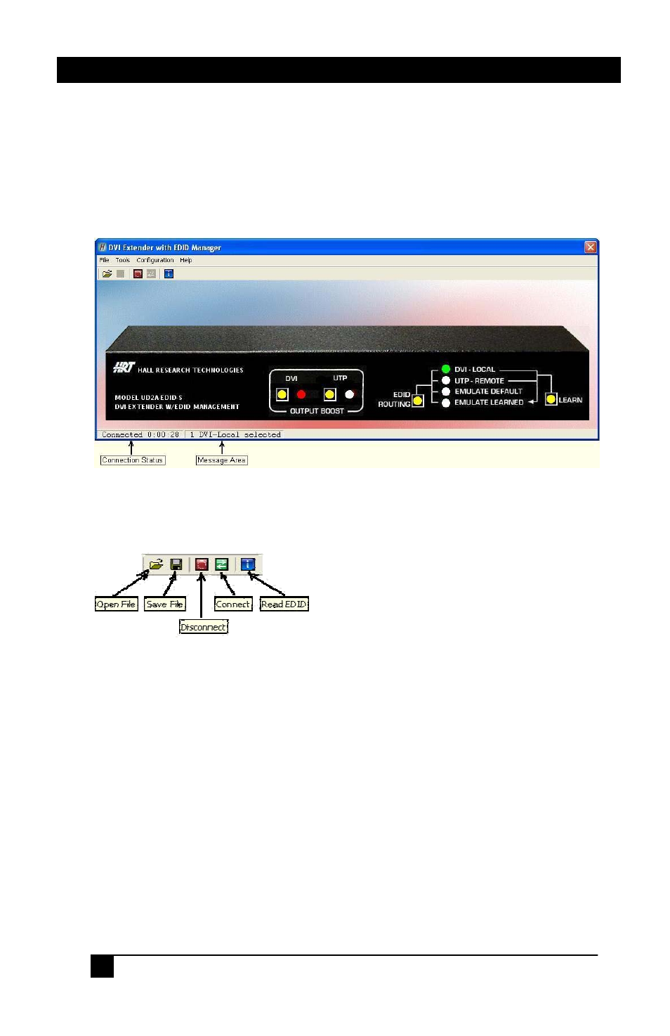
Once the communication is established between the UD2A-EDID
software and the UD2A-EDID-S, the Main window should display the
current state of the UD2A-EDID-S. Any change made either from the
front panel or from the GUI will be updated accordingly. Any selection
can be made by clicking on the buttons in the picture just like you were
pressing them on the front panel. Selections can also be made by selecting
the appropriate options under the Tools menu.
The Toolbar menu as shown in Figure 5 will have buttons enabled or
disabled according to the current state of the UD2A-EDID-S.
EDID information read from the device connected to the senders INPUT
DVI connector, receivers OUTPUT DVI connector, from previously
stored information in memory such as EMULATE DEFAULT or
EMULATE LEARNED, or from an opened data file will be shown in a
window similar to Figure 6 below.
If no device is connected to either senders INPUT DVI connector or the
receivers OUTPUT DVI connector, or no information is stored in
memory, all FF hex characters will be shown.
Figure 4 – Main
Figure 5 – Toolbar Menu