2 connecting the sender local outputs, 3 connecting the sender to the receiver, 4 connecting the receiver outputs – Hall Research U97-Ultra-2B-S User Manual
Page 9
U97-ULTRA
10
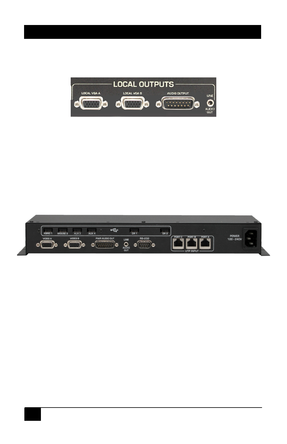
2.2 Connecting the Sender local outputs
The sender has buffered outputs for connection of two LCD’s, plus direct loop-thru of the
DB15 and 3.5 mm audio inputs.
Close-up of Sender Local Outputs
2.3 Connecting the Sender to the Receiver
You typically need 3 UTP or STP cables to connect to sender to the receiver. See
Section 1.1 and 1.2 for further details.
2.4 Connecting the Receiver outputs
The receiver outputs are shown below.
Receiver Rear Panel
Connect display devices such as two LCD’s to the VIDEO ‘A’ & VIDEO ‘B’ connectors of
the receiver.
Connect a LINE AUDIO OUT from the receiver to any standard PC external speakers
(powered) using male to male 3.5mm audio patch cable.
If an amplified audio output level is desired, connect the receiver’s PWR AUDIO OUT
connector to the desired passive speaker. The volume of output is the same as that of
the input at the sender.
Regardless of which input is connected at the Sender, both audio outputs on the
Receiver are simultaneously active. For example you can hookup 3.5mm input to the
Sender and a Passive speaker to the db15 connector of the Receiver.