Hall Research U97-Ultra-2B-S User Manual
Page 11
U97-ULTRA
12
In CAL-mode, the Sender disconnects the user’s video input and substitutes an internally
generated test pattern. The Receiver automatically recognizes the CAL mode and lights
the video adjust LEDs
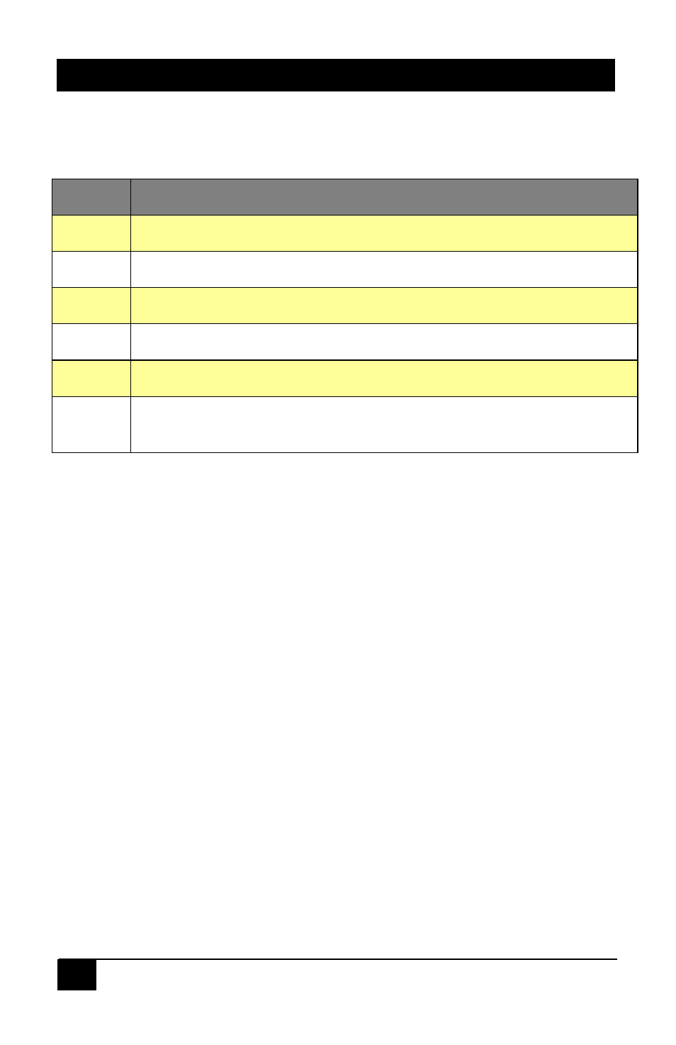
Lit LED Mode
A
Calibrating Video A (Select, Up, and Down buttons adjust Video A output)
B
Calibrating Video B (Select, Up, and Down buttons adjust Video B output)
RED
Up and Down buttons adjust the horizontal position of Red components
GRN
Up and Down buttons adjust the horizontal position of Green components
BLU
Up and Down buttons adjust the horizontal position of Blue components
R+G+B When all 3 LED’s are lit the Up and Down buttons adjust the high-frequency
gain of all video components
Notes:
1) Press and hold the UP or Down buttons to ramp through the adjustment
2) When you reach the max or min limit of any adjustment all 3 LEDs flash
3) To quickly jump to minimum setting press both UP and Down buttons together
2.5 Adjusting the Video to compensate for long UTP cables
There are two ways to get into the calibrate-mode to adjust the video:
The first and recommended method is to use the VIDEO ADJUST switch on the
Sender and set it to CAL. This puts the Receiver in the calibrate mode and also
activates a test pattern. The Receiver stays in this calibrate-mode until the
VIDEO ADJUST switch is set back to RUN.
The other way to enter the calibrate-mode is to hold down the SELECT button
for 3 seconds at the receiver, in this case the test pattern will not be displayed so
the video output is the same as that connected at the Sender. If there is no user
activity on the front panel for 1 minute, the receiver will time out and switch back
to the run-mode.
The following figures show how an image can be adjusted to become perfect by using
the receiver front panel controls.