9 flat surface installation - horizontal collector, 5 collectors – Glow-worm Clearly Solar - A-Frame User Manual
Page 25
25
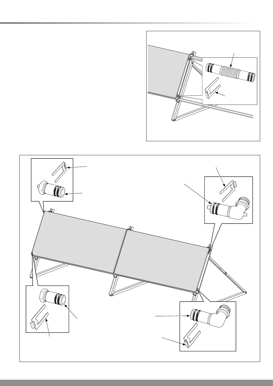
9 Flat Surface Installation - Horizontal Collector
Diagram 9.9
15157
PIPE
COUPLING
SECURING
CLIP
Remove the plugs from the openings of the collector and
insert the pipe couplings up to their stops, see diagram 9.9.
Slide the retaining clips into place to secure the pipe
couplings.
NOTE: The collector design is symmetrical and does not have
a top or bottom.
Place the next collector on the lower mounting rail and slide
towards the first collector.
Secure the pipe couplings to the second collector with the
securing clips.
Tighten the clamping assemblies of the first collector with the
socket/ combination wrench (SW13), see diagrams 9.10 and
9.11.
With regards to the hydraulic system you have chosen, insert
and secure the hydraulic connections, see diagram 9.10.
Insert the collector sensor into the appropriate elbow (flow,
top), see diagram 9.10. The collector sensor is packed with
the Fluropro controller, part no. 0020054960.
Mount the plug with the bleed valve (vent) in the opposite top
position.
Diagram 9.10
15158
FLOW
ELBOW
(with sensor)
SECURING
CLIP
RETURN
ELBOW
(inlet)
SECURING
CLIP
SECURING
CLIP
UPPER PLUG
WITH VENT
SECURING
CLIP
LOWER PLUG
TOP AND BOTTOM OR DIAGONAL FLOW
1-5 Collectors