FeiYu Tech FY-31AP User Manual
Page 5
Guilin Feiyu Electronic Technology Co., Ltd
Guilin Feiyu Electronic Technology Co., Ltd http://www.feiyudz.cn E-mail: [email protected] Page 5
21. FY-31AP installation: Orientation, Position and level
a) The FY-31AP has an arrow printed on the top of it. Orientate the
arrow towards the front of the craft (i.e. direction of flight).
b) When installing, please keep the FY-31AP horizontal and as close as
possible to the "
Centre of gravity
" (COG) of the aircraft.(as the
following diagram)
c) The control benchmark of FY-31AP is the NEUTRAL VALUE position.
But when install the dip angle between FY-31AP and the plane still
should be not more than 15 deg .
d) If there is deviation between the neutral value position and the
plane’s level flight, it may cause deviation of fixing plane’s level
flight. See next topic. But these deviation can be amend by recording
the neutral value. Please refer “RECORDING YOUR AIRCRAFT
NEUTRAL VALUE.”
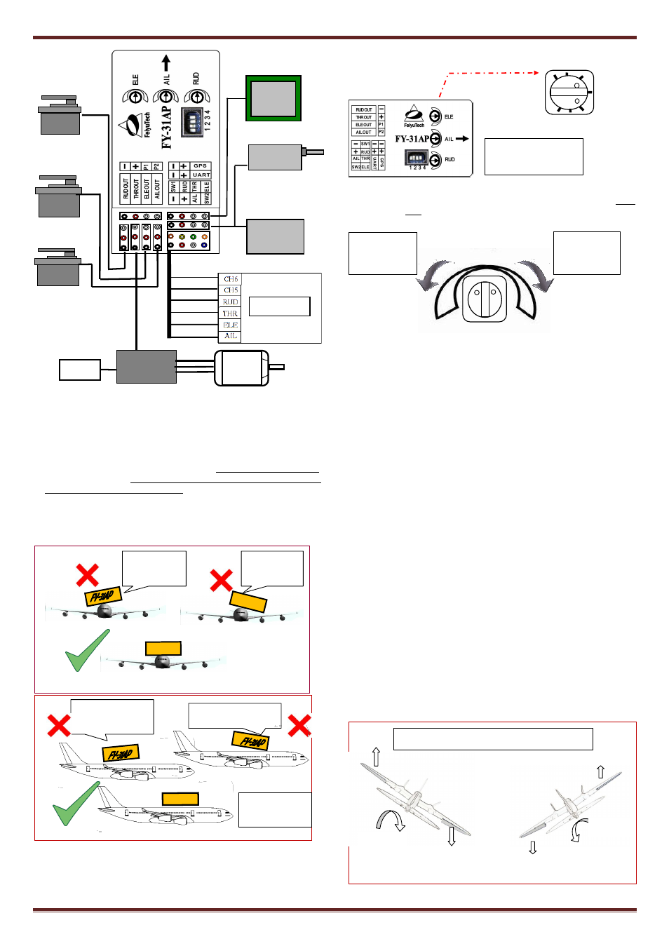
22. Adjustment Dials for ELE, AIL and RUD
1. There are 3 adjustment dials on the FY31AP. Each dial controls both
gyro gain
and
servo direction during auto stabilization.
2. Gyro Gain: The further away from Centre (12 O’clock) the higher
the Gyro gain (sensitivity). Too low gain result is poor auto
stabilization, too high gain will cause oscillations of the aircraft. You
need to adjust the gain setting based on the requirement of your
aircraft.
3. Servo Direction: The dials also control the direction of your servo
movement. Turning it clockwise or counter clockwise from 12
O’clock will change the direction of your servos during stabilized
flight against tilting, roll and yaw.
23. CONTROL SURFACE MOVEMENT CHECK
Install FY31AP as recommended in this manual, then proceed to confirm
correct control surface movement direction in Mode 2 or Mode 3.
1.
In Manual mode (stabilization deactivated) confirm that the control
surfaces do to react when your aircraft is tilted or rolled.
2.
Activate Mode 2 (Auto stabilize mode) and observe the movement
direction of Aileron, Elevator and Rudder. The direction should be as
shown below. If direction is wrong, turn the appropriate dial to the
opposite side of 12 O’clock to get the action direction correct:
AILERONS - Roll the plane to see the following action:
Incline the plane to the right (roll right). The ailerons should give a
control signal to counter this roll direction (see below). Same as when
rolled to the left. If the ailerons move correctly, the knob has been
turned in the right direction. You can now adjust gain by moving
nearer (low gain) or further away (high gain) from center;
If the ailerons do not follow the movements shown above, simply turn
the aileron knob to the opposite side (beyond centre). You should
now see the correct aileron movement.
Right aileron
automatically
move downwards.
Roll right
Left aileron
automatically
move upward.
Right aileron
automatically
move upwards
Roll left
Left aileron automatically
move downwards
Aileron Movement In Auto Stabilization Mode
The 3 dials control
both gain & servo
direction.
+100 Max
-100 Max
0 Min
Plane nose will pitch
down when in Auto
Stabilization Mode.
Plane nose pitches up when
in Auto Stabilization Mode.
Plane pitch remains
level when in Auto
Stabilization Mode
FY-31AP
Plane will roll to the
left when in
Stabilized Mode
FY-31AP
Plane roll remains level when in Auto Stabilization Mode
FY-31AP
FY-31AP will roll to
the right when in
Stabilized Mode
Max Gyro Gain
Max Gyro Gain
Servo direction
change in
Mode 3 & 2.
Servo direction
change in
Mode 3 & 2.
12 O’clock
Min Gyro Gain
OSD
Module
THR OUT
ESC
AIL OUT
RUD OUT
ELE OUT
Battery
Brown
Green
Blue
Yellow
Red
Black, red, white
RC receiver
GPS
Module
Electric
Motor
Data Radio