FeiYu Tech FY-31AP User Manual
Page 3
Guilin Feiyu Electronic Technology Co., Ltd
Guilin Feiyu Electronic Technology Co., Ltd http://www.feiyudz.cn E-mail: [email protected] Page 3
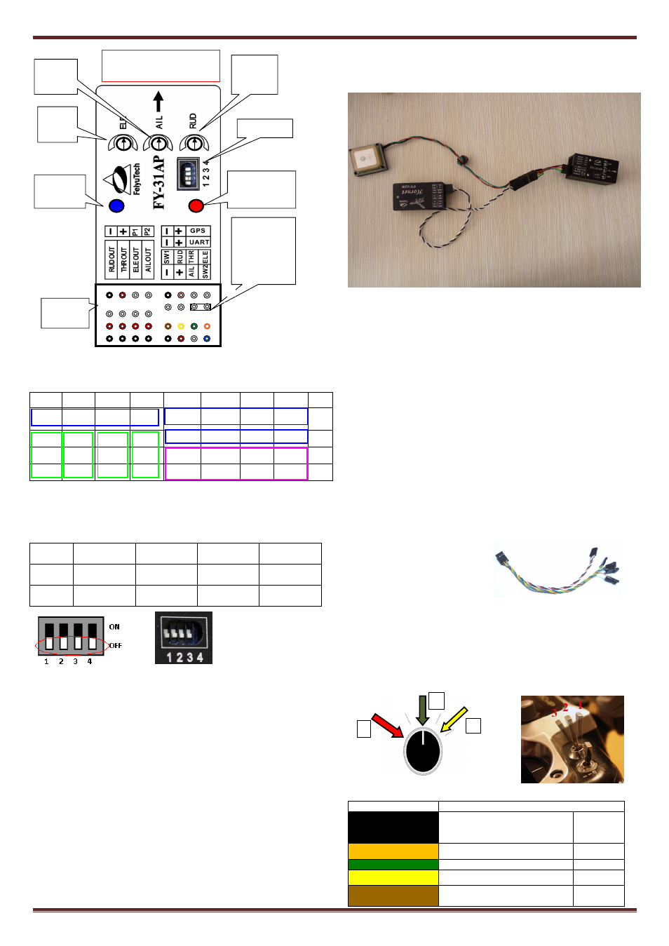
Pin interface to sort the list
8
7
6
5
4
3
2
1
NO.
GND
Power
P1
P2
GND
3.3V
TX0
RX0
Ⅰ
RUD
THR
ELE
AIL
GND
Power
TX1
RX1
Ⅱ
Power Power
Power
Power
Switch 1 Rudder Throttle Elevator
Ⅲ
GND
GND
GND
GND
GND
Power
Aileron Switch 2
Ⅳ
NOTE: The pin”I-1,2,3,4”is for the GPS module, “I-3”pin output
+3.3V, so please don’t supply to this pin, or will burn the
FY-31AP.
DIP Switch Function:
Switch
number
1
2
3
4
ON
For Factory
use only
Flight Mode
Selection
Flight Mode
Selection
Adjust flight
patterns
OFF
Always OFF
position
Flight Mode
Selection
Flight Mode
Selection
Normal
mode
Note:
In this manual, the direction for all the DIP switches is shown by
white color .
the position for the DIP switch 1 is OFF, if it was put in ON, then the
FY-31AP cannot work normally.
GPS features
The FY31AP GPS pin interface consist of: GND, 3.3V voltage, TX0, RX0.
The characteristics are:
Baud Rate : 38400
Interface Features: TTL level
Data bits: 8
Stop Bits: 1
Parity: None
Connect the above to the GPS Receiver. The GPS data protocol is a
standard NEMA0183 and the statement must be $ GPRMC, $ GPGGA.
NOTE: The pin”I-1,2,3,4”is for the GPS module, “I-3”pin output
+3.3V, so please don’t supply to this pin, or will burn the
FY-31AP.
TXO pin interface is used to output FY-31AP
(above firmware V2.1)
data,
and connect Hornet-OSD
(above firmware V1.6)
.
Horner-OSD can be connected to the FY-31AP high-speed data outlet.
You need a 4p Y cable, the Hornet - OSD
(above firmware V1.6).
data cable and GPS module connected to the FY-31AP(
above firmware
V2.1)
’s GPS interface. Connection diagram is as follows:
UART Interface
The UART pin interfaces consist of: GND, power, TX1, RX1. The
characteristics are as follow:
Baud Rate: 19200
Data bits: 8
Stop Bits: 1
Parity: None
Interface features: TTL
The pin interfaces output telemetry data. This interface connects to the
data radio, PC computer serial port or OSD module. You can set the
flight route, navigation and control parameters of FY31AP by this
interface. The port is also used to upgrade FY31AP firmware.
Please read the procedure for the firmware upgrading.
FY-31AP Electrical Connection and Diagram
a) Power supply
The FY-31AP operates between 4 to 6 volts input.
FY-31AP is powered via the Receiver connection.
If your plane is Electric powered, the Receiver power supply is
normally from the ESC built-in Battery Elimination Circuit (BEC).
However, we highly recommend that a separate BEC with a 3A
output.
For Gas or Nitro powered planes, you will require a battery to power
the Receiver and FY-31AP.
b) Connections The FY31AP is
connected to your RC Receiver
via a 6 wire cable. You need a
minimum 6 Channel RC
Receiver.
FY-31AP requires a minimum
of 6-channel RC receiver.
4 Receiver channels are used for aileron (channel 1), elevator
(channel 2) ,throttle (channel 3) and rudder (channel 4) signal
output. Connect these 4 receiver output signals to the FY-31AP with
the supplied wires (pay attention to the color of each channel ).
2 free Receiver channels are required to control the FY-31AP Flight
Modes (3-position switch or dial knob, ”SW1”) and Autopilot
Mode (3-position switch or dial knob, ”SW2”).
c) Note that the wire is arranged according to color :
Wire color
Receive channel
White
(bundled with red
& black)
aileron
Channel 1
orange
elevator
Channel 2
green
throttle
Channel 3
yellow
rudder
Channel 4
brown
SW 1
Any free channel controlled by Channel 5
1
2
3
POINT ARROW FORWARD
(TOWARDS FLIGHT DIRECTION)
2
3
4
5
6
7
8
1
Function DIP
switch
J
umper installed
during gyro
initialization.
Do not insert
jumper during
normal use.
Red LED: the GPS
status & vibration
level indicator
Rudder
sensitivity
knob
Aileron
sensitivity
knob
Elevator
sensitivity
knob
Blue LED:
Flight mode
indicator.
Interface pin
panel
Ⅳ
Ⅲ
Ⅱ
Ⅰ