FeiYu Tech FY-31AP User Manual
Page 4
Guilin Feiyu Electronic Technology Co., Ltd
Guilin Feiyu Electronic Technology Co., Ltd http://www.feiyudz.cn E-mail: [email protected] Page 4
3-way switch or dial knob
blue
SW 2
Any free channel controlled by
3-way switch or dial knob
Channel 6
17. Vibration damping
A. FY-31AP is vibration-sensitive. To optimize its stabilization capability,
vibrations reaching the unit must be kept at a minimum.
B. When installing this flight stabilizer, we highly recommend that you
install it with the supplied vibration absorbing pads (dampers).
C. The algorithm in the FY-31AP compensates for normal levels of flight
vibration. However, if the vibration experienced by the unit exceeds
the acceptable level, it will not work normally or may even stop
working altogether.
D. To keep vibration at a minimum, install the FY-31AP away from the
engine or any other vibration sources.
E. The included shock-absorbing pads will
meet the damping requirements for
electric powered aircrafts and most gas
/ nitro planes.
F. The FY-31AP is supplied with the
double-sided foam padding dampers.
Please use them as shown:
Checking for Vibration Levels
Even with the shock absorbing mount, your
aircraft installation may not meet the damping requirements of the FSS.
To confirm correct vibration damping, please follow this procedure:
A. After connecting all wires between the FY-31AP,Receiver and ESC,
install the unit as recommended (ensure correct orientation).
B. Run the plane engine or motor at different throttle levels. DO NOT
TAKE OFF.
C. Move the throttle level to different positions and maintain it for 20
seconds at each position.
D. At each throttle position, observe the state of the red LED light. If it
stays OFF, that means your vibration level is acceptable.
E. If instead the red LED lights up bright and stays ON solid, then the
vibration dampening is not enough. You will need reduce the level of
vibration on your aircraft, add additional dampening support or
change the installation location.
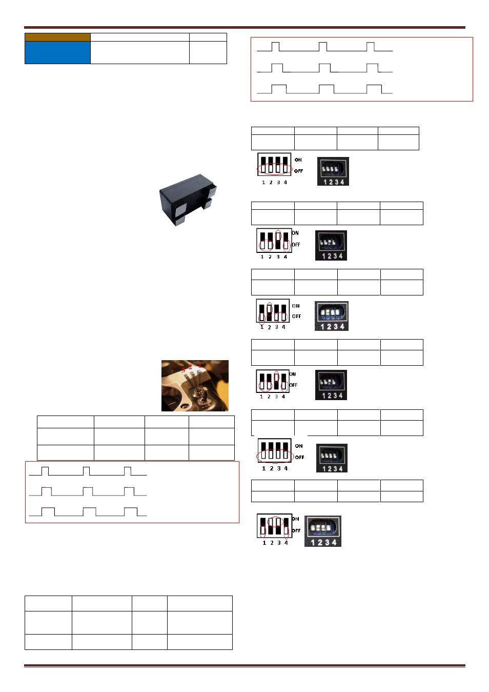
18. SW 1 and SW 2 : Switch Settings for FY31AP
a. SW-1 Flight Modes
The FY31AP has 3 Flight modes
controlled via SW-1. To select the modes,
use a free Receiver channel controlled via
a 3 way-switch:
FY-31AP flight modes
SW-1 signal output 900-1200us
1200-1800us
1800-2100us
Functional mode
Deactivated
Mode
Auto Stabilize
Mode
Navigation
Mode
Blue LED light
indicator
continuous flash Stay on solid
Single flash
Note: Navigation Mode: means one of the three modes. Path Navigation mode,
Fixed altitude flight mode and Heading lock flight mode. You can select via the
GCS Software. The default mode is Path navigation mode.
b. SW-2 Autopilot Modes
FY31AP Autopilot Modes is controlled via SW-2.
IMPORTANT: The Autopilot Mode (SW-2) has controlling priority
over the Flight Modes (SW-1). If you wish to use the Flight Mode
(SW-1), you must de-activate the Autopilot first.
SW-2 signal
output
900-1200us
1200-1800
us
1800-2100us
Functional
mode
Return To Launch
Mode
(RTL)
Cancel
Mode
Auto Circling Mode
(ACM)
Blue LED light
indicator
Continuous Double
flash each loop
/
Continuous flashing.
3 times each loop
19. Plane connecting layout
1) FY-31AP connection for traditional aircraft layout:
AIL OUT
ELE OUT
THR OUT
RUD OUT
Aileron
Servo
Elevator
Servo
Throttle
Servo
Rudder
Servo
2) FY-31AP connection for flying wing aircraft:
(with or without Rudder)
AIL OUT
ELE OUT
THR OUT
RUD OUT
Differential
Servo 1
Differential
Servo 2
Throttle
Servo
Rudder
Servo
3) FY-31AP connection for V tail aircraft with Aileron:
AIL OUT
ELE OUT
THR OUT
RUD OUT
Aileron
Servo
Differential
Servo 1
Throttle
Servo
Differential
Servo 2
4) FY-31AP connection for V tail aircraft without ailerons:
AIL OUT
ELE OUT
THR OUT
RUD OUT
Differential
Servo 1
Differential
Servo 2
Throttle
servo
Null
5) FY-31AP connection for traditional layout aircraft with no Aileron:
AIL OUT
ELE OUT
THR OUT
RUD OUT
Rudder
Servo
Elevator
Servo
Throttle
servo
Null
6) Camera Gimbal Stabilization:
AIL OUT
ELE OUT
THR OUT
RUD OUT
Roll Servo
Tilt Servo
Null
Pan Servo
* Note: The camera gimbal Roll, Tilt and Pan servos will counter any
linear movement of the camera mount. You can move the camera at any
angle and upon releasing the stick, the FY-31AP will maintain
stabilization at that angle. The FY-31AP is only suitable for the camera
gimbal control which the control accuracy is not very high.
20. Connection of FY-31AP
900-1200us Deactivated Mode
mode
1200-1800us Auto Stabilization Mode
1800-2100us Navigation Mode
900-1200us Return To Launch Mode
1200-1800us Cancel Mode
1800-2100us Auto Circling Mode