ENMET LC-8 User Manual
Page 11
LC S
ERIES
ENMET
9
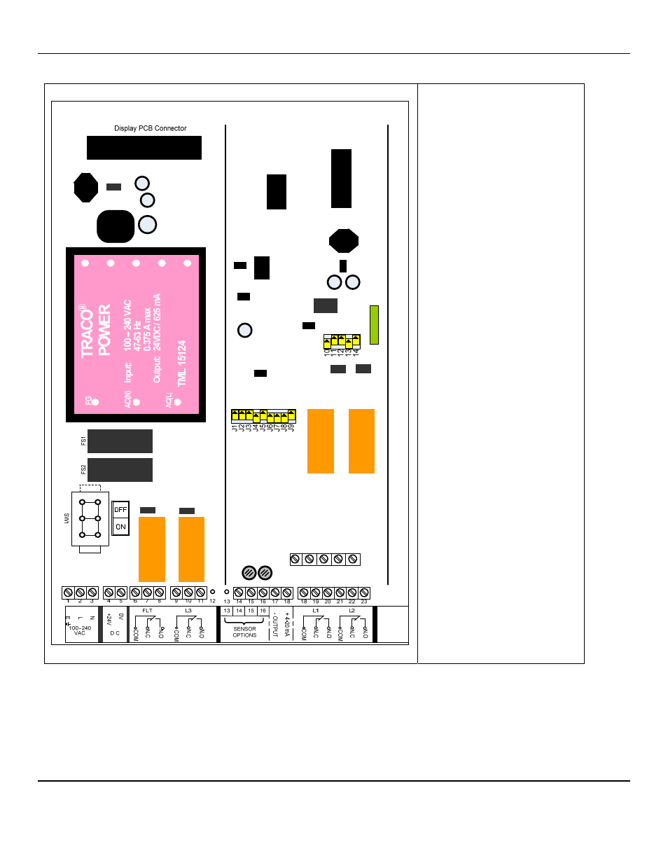
3.1.5 Connections LC4
LC4
Chanel 1
Connections
Sensor Options:
Pin 13: Signal In (1 – 5 Vdc)
Pin 14: Signal In (4-20mA)
Pin 15: Voltage Out to S/T
Pin 16: Ground to S/T
Chanel 2
Pins 25 to 36
The same functions as 13 to 24
Chanel 3
Pins 37 to 48
The same functions as 13 to 24
Chanel 4
Pins 49 to 60
The same functions as 13 to 24
An Earth ground is also provided
on the main PCB
The diagrams above show a pictorial representation of the various module positions within the LCU Series Control Units
The power supply is situated on the LHS of the main PCB with the channel I/Os to the right of the PCB.
The microcontroller module and LCD display are mounted on the top of the front panel. This connects to the main PCB via a
single flat ribbon cable
Note: connections 12 & 13 may not be fitted on some variants.