Area must be declassified during this procedure, 0lel exit zero – ENMET EX-5100 User Manual
Page 7
EX-5100 C
OMBUSTIBLE
ENMET Corporation
5
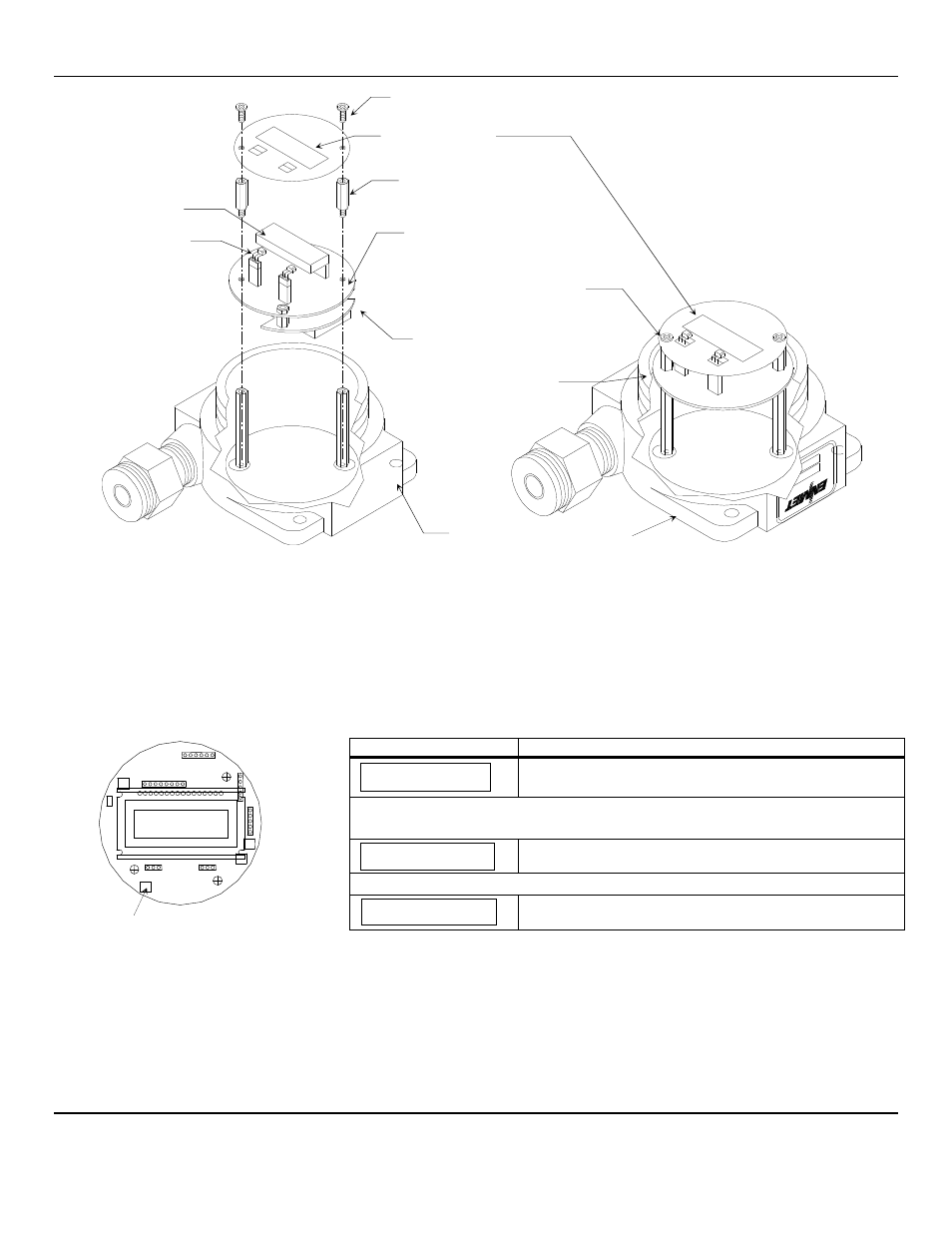
EX-5100
Interior Expanded View
EX-5100
Interior Assembled View
Figure 3: Terminal Positions EX-5100 Sensor/Transmitter
When wiring is complete, re-assemble the
EX-5100
. Use caution when installing the overlay so as not to damage the magnetic
switches. With the area declassified, apply power to the instrument. Allow the sensor transmitter to stabilize for 1 hour and
then enter the maintenance menu.
C
AUTION
:
Area must be declassified during this procedure.
To enter the maintenance menu hold the magnet over the
M
ENU
switch for 2 to 4 seconds
The chart below indicates the maintenance menu sequence see Figure 5 for a detailed maintenance menu flow chart.
Example of Display
Function
Normal Display Mode
Measurement of target gas
Hold the magnet over the
M
ENU
switch for 2 – 4 seconds to enter the Maintenance Menu
The Power/Fault LED will flash Green – Red to indicate the
EX-5100
is in Maintenance Mode
To exit the maintenance Menu and return to the Normal Display Mode:
If intended function Tap the magnet over
S
ELECT
switch
Tap the magnet over the
M
ENU
switch to advance to the Zero procedure
For adjusting Zero:
If intended function Tap the magnet over
S
ELECT
switch
Tap the
S
ELECT
switch once with the magnet, the display will alternate between [PV: 0] and [Zero]
At this point, tap the
M
ENU
switch once with the magnet. The display should now alternate between [Zero] and
[In 300] (+ or – 30). If not then, use POT 2, to adjust to 300(+ or – 30).
N
OTE
:
The
EX-5100
will automatically reset the zero point based on a stable signal if [Span] appears before you get the 300 set
then re-enter the zero cal again, to start the clock over.
Once the zero is set, you will see [Span] on the display. Tap the menu until [E
XIT
] is displayed, then tap select once to put the
instrument in the normal operation mode.
Sensor/Transmitter Enclosure
Cutaway View
Printed Circuit Board
(PCB)
Display Overlay Screws
(2 places)
Display Overlay Standoffs
(2 places)
Magnetic Switches
(2 places)
Magnetic Switches
(2 places)
Printed Circuit Board (PCB)
J4 and J8 Terminals are located
on the bottom side of PCB
Display Overlay
Display
Optional
Relay Output circuit Board
0LEL
Exit
Zero
P
OT
2 on PCB