3 heater voltage settings, 4 sensor replacement c, 0lel exit zero – ENMET EX-5100 User Manual
Page 15
EX-5100 C
OMBUSTIBLE
ENMET Corporation
13
5.3 Heater Voltage Settings
Heater Voltages are necessary for Catalytic sensors. They are preset at the factory and should not require field adjustment. Do
not adjust these voltages unless specifically instructed to do so by
ENMET
Corporation Technical Support Staff.
C
AUTION
:
Improper adjustment of heater voltages can damage sensors voiding any warranties and also alter the operating
characteristics of the sensor in such a way that the
EX-5100
may not respond to it’s target gas.
5.4 Sensor Replacement
C
AUTION
:
Area must be declassified during sensor replacement.
Sensors should be replaced when they can no longer be calibrated. Replacement sensor part numbers are listed in Section 6.0
of this manual. If you do not know the proper part number for your sensor, be sure to have the
EX-5100
serial number
available when contacting your Distributor or
ENMET
Corporation Technical Support.
To replace a sensor, it is necessary to open the transmitter housing.
Remove the overlay and screws retaining the PC Board in the enclosure. Refer to Section 3.2, Figure 3.
Remove the sensor connector J8 and sensor
Wire in the new sensor. Refer to the wiring Table in Section 3.2, Figure 3.
After the new sensor has been installed, it is suggested to allow the sensor to stabilize for 24 hours.
A Factory calibration must be performed.
To enter the maintenance menu hold the magnet over the
M
ENU
switch for 2 to 4 seconds
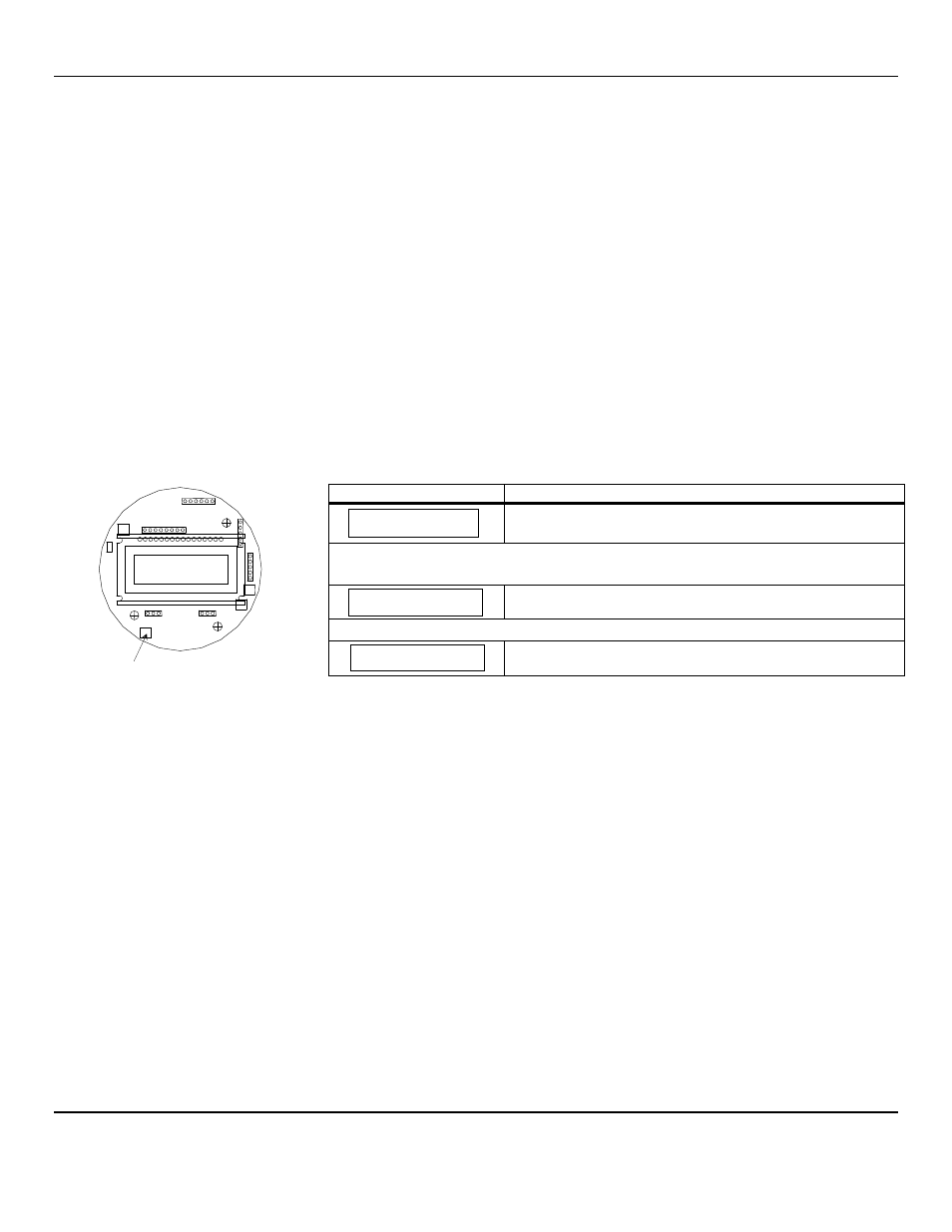
The chart below indicates the maintenance menu sequence see Figure 5 for a detailed maintenance menu flow chart.
Example of Display
Function
Normal Display Mode
Measurement of target gas
Hold the magnet over the
M
ENU
switch for 2 – 4 seconds to enter the Maintenance Menu
The Power/Fault LED will flash Green – Red to indicate the
EX-5100
is in Maintenance Mode
To exit the maintenance Menu and return to the Normal Display Mode:
If intended function Tap the magnet over
S
ELECT
switch
Tap the magnet over the
M
ENU
switch to advance to the Zero procedure
For adjusting Zero:
If intended function Tap the magnet over
S
ELECT
switch
Tap the
S
ELECT
switch once with the magnet, the display will alternate between [PV: 0] and [Zero]
At this point, tap the
M
ENU
switch once with the magnet. The display should now alternate between [Zero] and
[In 300] (+ or – 30). If not then, use POT 2, to adjust to 300(+ or – 30).
N
OTE
:
The
EX-5100
will automatically reset the zero point based on a stable signal if [Span] appears before you get the 300 set
then re-enter the zero cal again, to start the clock over.
Once the zero is set you will see [Span] on the display. Tap the menu until [Z
ERO
] is displayed.
Place the magnet over the
M
ENU
switch and hold for 2-4 seconds while viewing the Zero menu.
After 2-4 seconds, an F will appear on the far right hand side of the display. The F indicates that the instrument is in Factory
mode.
Perform the calibration Zero and Span procedures as outlined in Section 5.2. Be sure that the F is present when selecting the
Zero and Span functions.
The Factory calibration sets a calibration window for future standard instrument calibrations.
Only perform a factory calibration when installing a new sensor!!
0LEL
Exit
Zero
P
OT
2 on PCB