ENMET EX-5100 User Manual
Page 4
ENMET
Corporation
EX-5100 C
OMBUSTIBLE
2
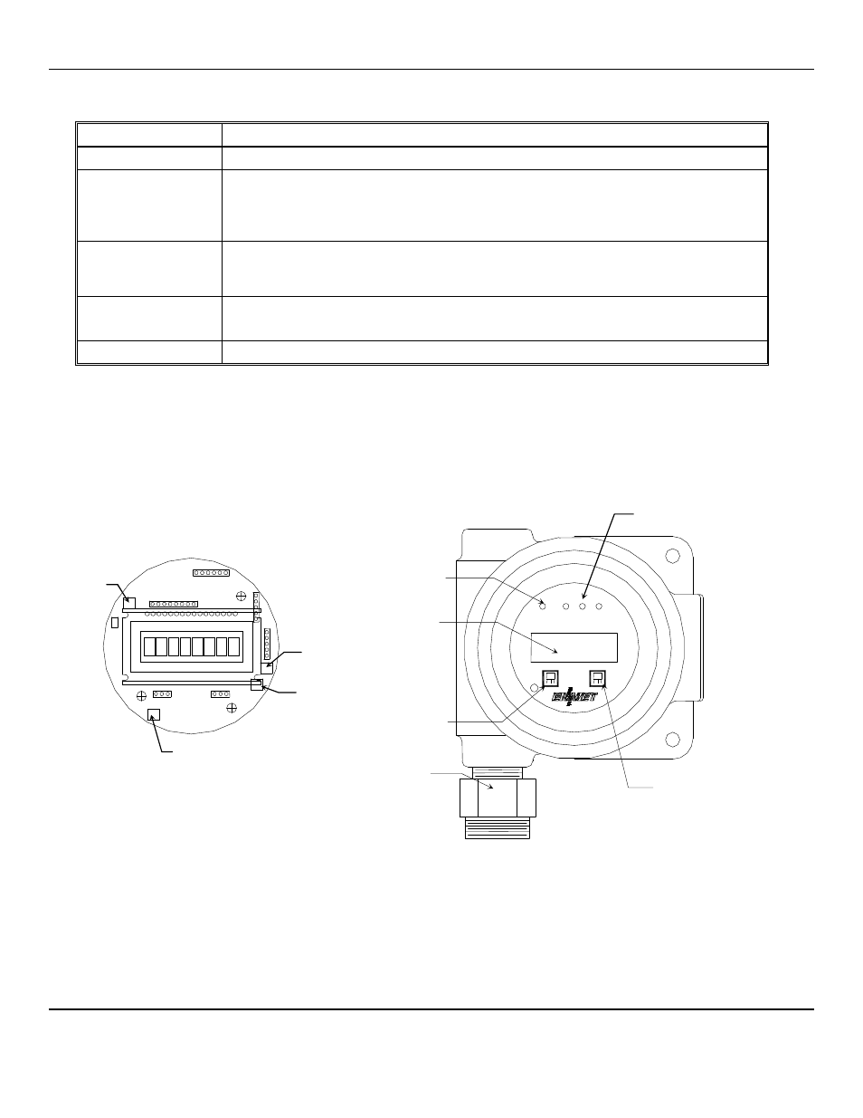
2.0 Features of the EX-5100
See Figure 1 for location of features:
Feature
Description
Display
LCD: Indicates the level of gas detected by sensor
Gain Potentiometer
(POT)
POT 1: Display contrast adjustment
POT 2: Combustible Sensor Zero adjustment, See Sections 3.2 and 5.4
POT 3: Combustible Heater Do not adjust unless advised by
ENMET
POT 4: Used with EX-5150-MOS (High Voltage) Do not adjust unless advised by
ENMET
Visual Alarms
LED indicators:
Power / Fault Indicator LED, Green / Red
Alarm (3) Indicator LED, Red
Magnetic Switches
M
ENU
: Advances the instrument display through menus (Zero, Span, Exit)
S
ELECT
: Selects the Zero, Span, Exit menu or sets proper calibration values for Zero or Span
Sensor
For sensing LEL levels of gas, see Table 2 and 3 for sensor types
Magnetic switches control the instrument maintenance functions. The switch locations are indicated by
M
ENU
and
S
ELECT
. A
magnetic field pulse is applied by momentarily putting the end of the magnet in proximity to the switch and then removing it.
Since the magnetic field penetrates the window, the enclosure cover is not removed in order to perform calibration.
Three alarm points are preprogrammed into the
EX-5100
sensor/transmitters. At each alarm point, an LED on the front panel
is activated. These internal alarm settings are independent of the 4-20mA output alarm values that can be set at a controller.
An optional relay board is available that will activate 0.5 Amp relay contacts at each alarm point, plus a fault relay.
Internal PCB View
External View
Figure 1: EX-5100 Features
Power /Fault
Indicator
Display
M
ENU
Magnetic switch
3 Alarm Indicators
S
ELECT
Magnetic switch
Sensor
Note: See Section 6.0
Replacement Parts for
sensor identification
Menu
Select
POT 3
POT 4
POT 2
POT 1
Note:
POT 1, 3 & 4 shown
for reference only.
Do Not Adjust