2 power supply, 3 inputs / outputs, Figure 2a: relay, input and output terminals – ENMET GSM-60 User Manual
Page 9
GSM-60
ENMET Corporation
6
3.2 Power Supply
The input power can vary from 100 to 240
V
AC
, 50/60 Hz. Mains power should be connected to the Power Input Terminal
J23
and the ground screw
J21
. See Figure 2 for location.
W
ARNING
:
Continuous gas detection and alarm systems (110
V
AC
/220
V
AC
/ 24
V
DC
/
12
V
DC
powered) become inoperative upon
loss of primary power. Contact factory for specifications and pricing of backup battery systems.
Upon supplying air and power to the instrument:
The green power on LED is lit.
The display backlight is lit, and instrument will step through a start-up sequence: unit serial number, software revision and
gases monitored may be shown on the display.
The instrument may go into alarm briefly, but the sensors stabilize quickly. If the instrument persists in alarm, acknowledge the
alarm by pressing the
AUDIO DEFEAT
/
ALARM ACKNOWLEDGE
switch. If alarm persists longer than 30 minutes, call
ENMET
customer service personnel.
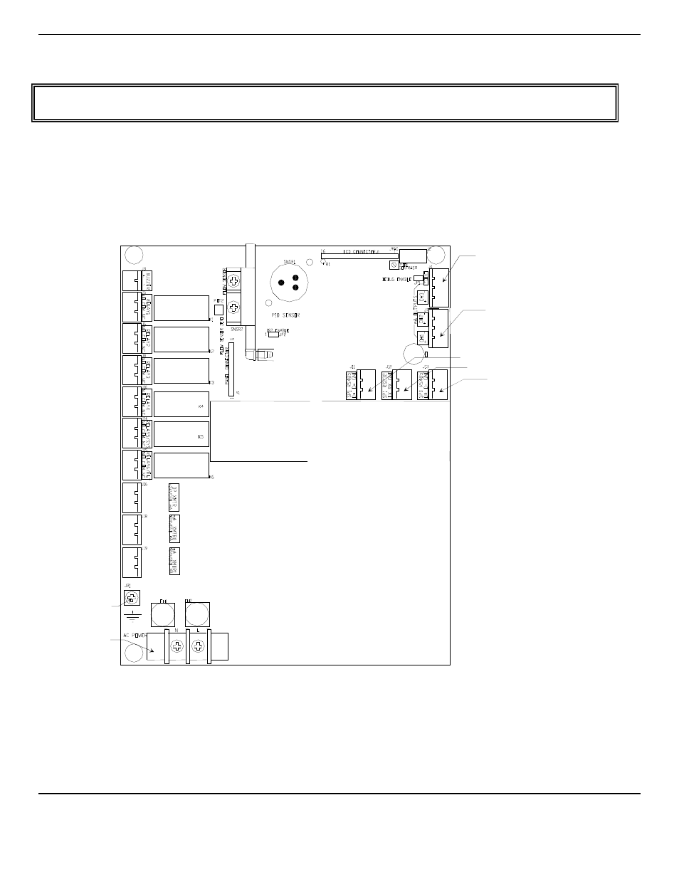
3.3 Inputs / Outputs
Two types of alarm outputs are available, relay contacts and 4-20mA outputs.
Figure 2A: Relay, Input and Output Terminals
Relay 1
Channel 1
Alarm 1
Relay 2
Channel 2
Alarm 1
Relay 3
Channel 3
Alarm 1
Relay 4
Channel 4
Alarm 1
Relay 5
Channel 1-4
Alarm 2
Relay 6
Ch 1-4 / System
Fault
Input Connector
24V
DC
GND
mA
Input Connector
24V
DC
GND
mA
Input Connector
24V
DC
GND
mA
Connector 2
Channel 3 & 4
4-20mA Output
Connector 1
Channel 1 & 2
4-20mA Output
Connector RS485
Connector RS232
Connector RS485
Ground Screw J21
Power Input
Terminal J23