Recommended wire gauge – ENMET GSM-60 User Manual
Page 10
GSM-60
ENMET Corporation
7
3.3.1 Sensor/Transmitter Connection
Sensor/Transmitters are connected to the
GSM-60
control unit with two or three-conductor wiring, use the correct oiltight
fitting. Size of wire depends on the distance between the sensor/transmitter and the control unit.
See Recommended Wire Gauge Table below.
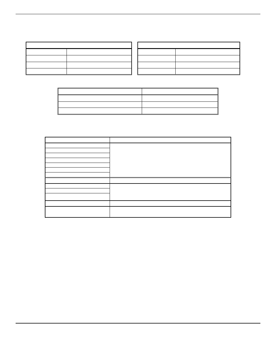
2 Wire for Sensors/Transmitter
3 Wire for Sensors/Transmitter
Position
Function
Position
Function
1
Power +24
V
DC
1
Power +24
V
DC
2
Not Used
2
Power Ground
3
Signal/Return to Ground
3
Signal
Recommended Wire Gauge
Distance from Sensor to Control Unit
Recommended Wire Gauge
< 500 feet
16 AWG
501 – 800 feet
14 AWG
Longer Distances
Contact Factory
N
OTE
: Sensor Location
Gases have different densities. Some are heavier than air and concentrate at the bottom of a space. Some are lighter than air
and gather at the top. Consider the density of the gas you want the sensor to detect when you install the sensor. Some
examples are given below.
Heavier than Air Gas
Sensor Location
Bottled LP (liquefied petroleum)
Interior wall; 18-24" from floor.
•
D
O
N
OT
locate directly above or beside gas appliances (ovens,
heaters).
•
Avoid locating anywhere near a vent or window or near an outside
doorway.
Propane
Butane
Gasoline
Trichloroethylene
Vaporized hydrocarbons
Hydrogen sulfide
Lighter than Air Gas
Sensor Location
Natural gas (methane)
Near ceiling.
•
D
O
N
OT
locate directly above appliances where it is subject to direct
exposure to heat or steam.
Ammonia
Hydrogen
Same Density as Air Gas
Sensor Location
Carbon Monoxide
4-6 feet above the (generally uniform) floor.
•
D
O
N
OT
locate in direct air currents of windows, doors, or vents.
If you have a question involving the location of a unit or sensor, please contact your distributor or
ENMET
personnel. A
technician will analyze the question and recommend a location.
3.3.2 Relay Contacts
Relay contacts are available for each alarm; these are
SPDT
, rated at 10Amp at 110
V
AC
, and may be latching or non-latching
as required by the application.
They are accessed on the terminals next to each relay see Figure 2 & 2A. The contact positions are noted on the circuit board
next to each terminal.
Relays may also be configured as failsafe or non-failsafe. The default alarm relay configuration is for latching mode, and
failsafe. They may be reconfigured in the maintenance menu. See section 5.3.5 & 5.3.6
The PC Board is labeled for the relays in their un-energized state. If the relay is configured for failsafe, then this is also the alarm
condition state. Non-failsafe configured relays in the alarm state, are the reverse of the PC board labeling. Note that the
Fault(FLT) relay cannot be set to operate in a Non-Failsafe mode. Please see the Table 1: