Table 1 : relay failsafe settings, Table 2: sensor output, 4 installation verification – ENMET GSM-60 User Manual
Page 11
GSM-60
ENMET Corporation
8
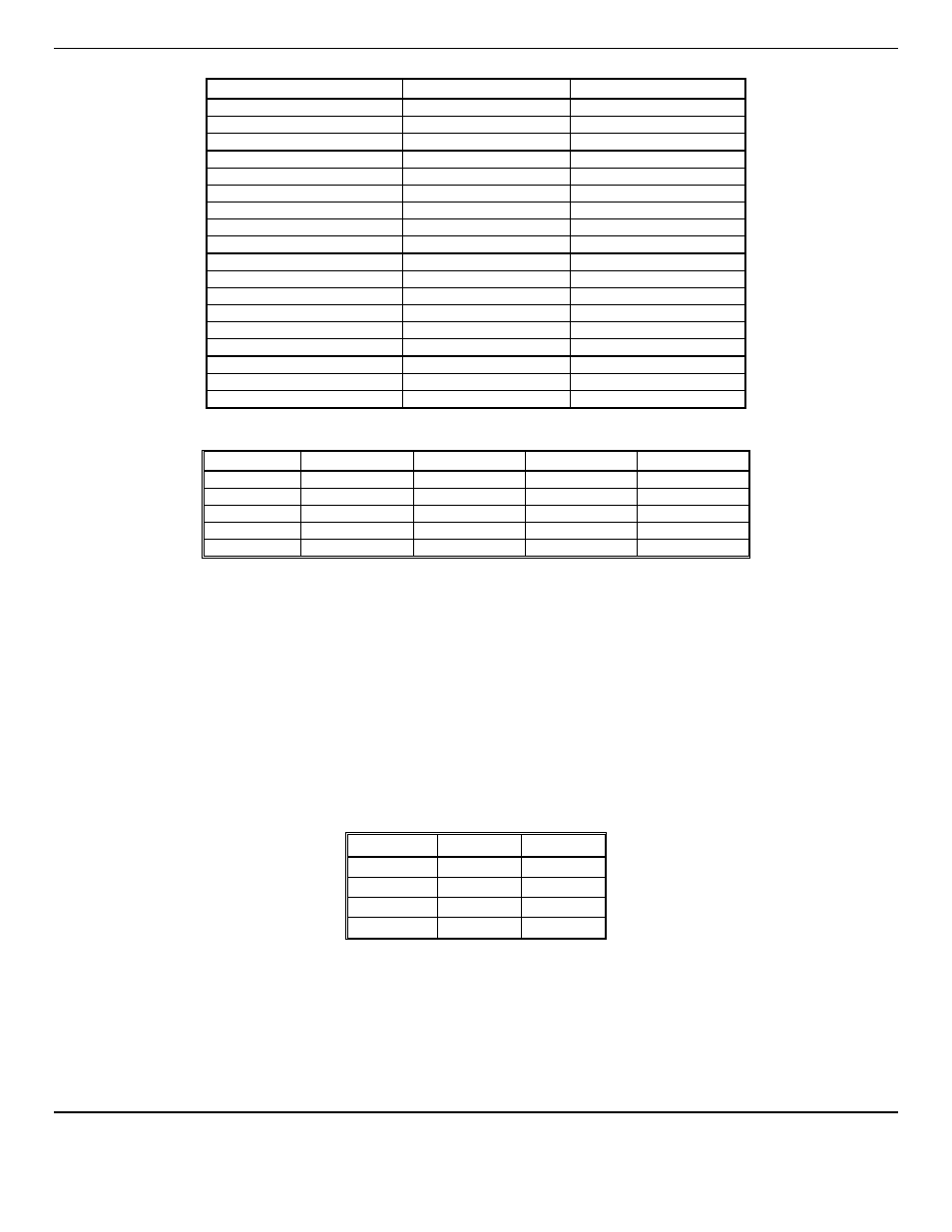
Table 1 : Relay Failsafe Settings
Position
Failsafe-Alarm
Non-Failsafe-Alarm
J5
Relay 1 - NO
Normally Open
Normally Closed
J5
Relay 1 - COM
Common
Common
J5
Relay 1 - NC
Normally Closed
Normally Open
J6
Relay 2 - NO
Normally Open
Normally Closed
J6
Relay 2 - COM
Common
Common
J6
Relay 2 - NC
Normally Closed
Normally Open
J8
Relay 3 - NO
Normally Open
Normally Closed
J8
Relay 3 - COM
Common
Common
J8
Relay 3 - NC
Normally Closed
Normally Open
J10
Relay 4 - NO
Normally Open
Normally Closed
J10
Relay 4 - COM
Common
Common
J10
Relay 4 - NC
Normally Closed
Normally Open
J14
Relay 5 - NO
Normally Open
Normally Closed
J14
Relay 5 - COM
Common
Common
J14
Relay 5 - NC
Normally Closed
Normally Open
J15
Relay 6/FLT - NO
Normally Open
N/A
J15
Relay 6/FLT - COM
Common
N/A
J15
Relay 6/FLT - NC
Normally Closed
N/A
Relays can be linked to specific alarms. The table below shows the default relay links. They may be changed in the
maintenance menu if required. See Section 5.0.
Channel 1
Channel 2
Channel 3
Channel 4
Relay 1
Low Alarm
Relay 2
Low Alarm
Relay 3
Low Alarm
Relay 4
Low Alarm
Relay 5
High Alarm
High Alarm
High Alarm
High Alarm
In addition, there is a fault relay, which changes state whenever the instrument is in a fault condition. The contact positions are
noted on the circuit board next to each terminal. See Figure 2A. The coil of this relay is energized when the instrument is in
the non-fault state; the contact conditions given on the circuit board next to the terminal, are for the non-energized state, which
is identical to the fault state.
These relay contacts can be used to operate auxiliary alarms or other functions. It is recommended that power for auxiliary
equipment be supplied from an independent power source, separate from the
GSM-60
. Place a hole in the enclosure for a wire
exit, and use appropriate cable fittings. Be sure to note the location and depth of hardware inside the enclosure.
3.3.3 Optional 4-20mA Outputs
Isolated 4-20 mA outputs are available for data logging or other purposes. An output is supplied for each sensor supplied in a
particular instrument, and can be added when a sensor is added in the field. These outputs are available on the Connector 1 for
channels 1 & 2 and Connector 2 for channels 3 & 4.
4mA corresponds to a sensor reading at the bottom of the instrument range and 20mA corresponds to a full scale reading.
Standard ranges are shown in Table 2.
Table 2: Sensor Output
Sensor
4mA
20mA
CO
0
50
O2
0
30
CO2
0
5000
HC
0
100
Wiring requirements are the same as for the relays.
3.4 Installation Verification
All instruments are calibrated at the factory. You may, if a calibration kit is available, calibrate the any and all gas channels of
the instrument 24 hours after installation to verify proper installation and instrument operation. See Section 5.0, Maintenance,
for calibration instructions. Calibration is also recommended after the first month of operation. Subsequent calibrations should
be performed every 3 months. The dew point sensor can not be calibrated in the field.