6 operational menu, Figure 5: gsm-60, Operation menu flow chart – ENMET GSM-60 User Manual
Page 14
GSM-60
ENMET Corporation
11
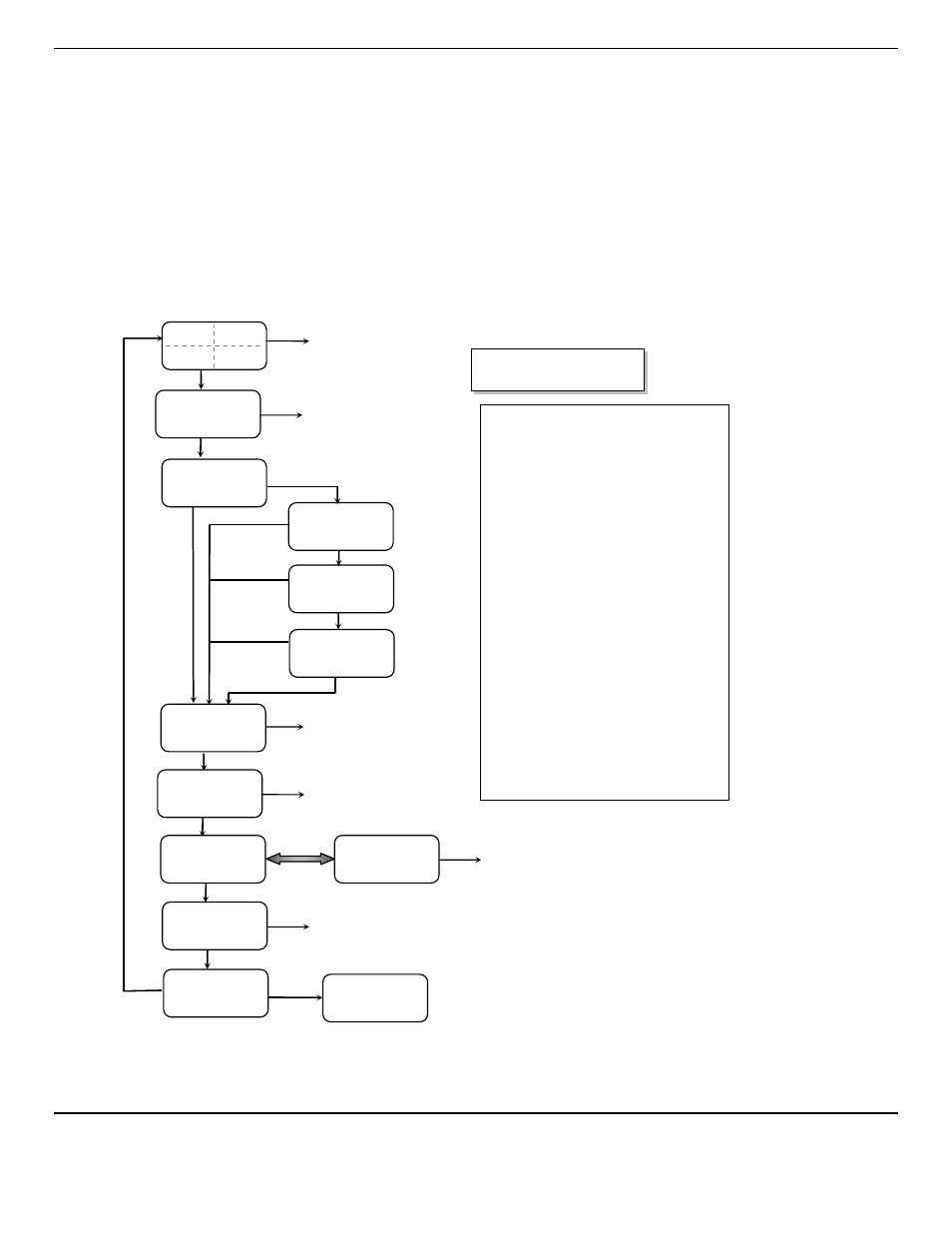
4.6 Operational Menu
The operational menu allows the user to:
View alarm set point concentration values
View alarm ascending/descending trigger, latching and delay configurations
Enter the maintenance menu with the proper Password.
The operational menu is accessed with the
OPTION
and
SELECT
switches. The operational menu flow chart is shown in Figure
5,
Pressing the
OPTION
switch is indicated with a "O"
Pressing the
SELECT
switch is indicated with a "S".
If the instrument is left at any location in the operational or maintenance menus, other than the operational display, with no
action taken for a period of 45 seconds, it returns to the operational display.
Figure 5: GSM-60
Operation Menu Flow Chart
O
S
CH-1
CH-3
CH-2
CH-4
O = Press Option switch
S = Press Select switch
O
No
Function
Λ
L10 A1 vL19.5
vL-40
Λ
D 500
O
No
Function
S
S
Λ
L20 A2
Λ
23.5
Λ
L39
Λ
1000
O
No
Function
S
Enter Maint Menu
Enter Password
_
See Maintenance Menu Diagram
O
S
for each active channel
CH1 SCALE (CO)
0 – 50
PPM
S
CH3 SCALE
(O2)
0.0 – 30.0 %
CH2 SCALE (H2S)
0 – 50
PPM
S
CH4 SCALE (CO2)
0 – 5000
PPM
S
O
O
O
Displays are examples of gases:
Channel 1 = Carbon Monoxide
Channel 2 = Hydrogen Sulfide
Channel 3 = Oxygen
Channel 4 = Carbon Dioxide
Displays are examples of Alarms
Λ
- Indicates alarm triggered on
increasing value of reading
v - Indicates alarm triggered on
decreasing value of reading
Displays are examples of Alarms
L
– Indicates alarm is in latching
mode.
(no
L
present) – Indicates alarm
is in non-latching mode.
Displays are examples of Alarms
D
– Indicates alarm is in
Differential Setting.
(no
D
present) – Indicates alarm
is in Standard Setting.
ALARM1 Delays
(Seconds)
O
S
No
Function
S
50 mASPAN 30.0
68
5000
O
No
Function
5
5
5
5
Alternating
S
Relays
1 2 3 4 5 6
✻=ON
✻✻✻✻✻✻
O
No
Function