3 circuit board features, Figure 2: gsm-60, Interior features – ENMET GSM-60 User Manual
Page 7
GSM-60
ENMET Corporation
4
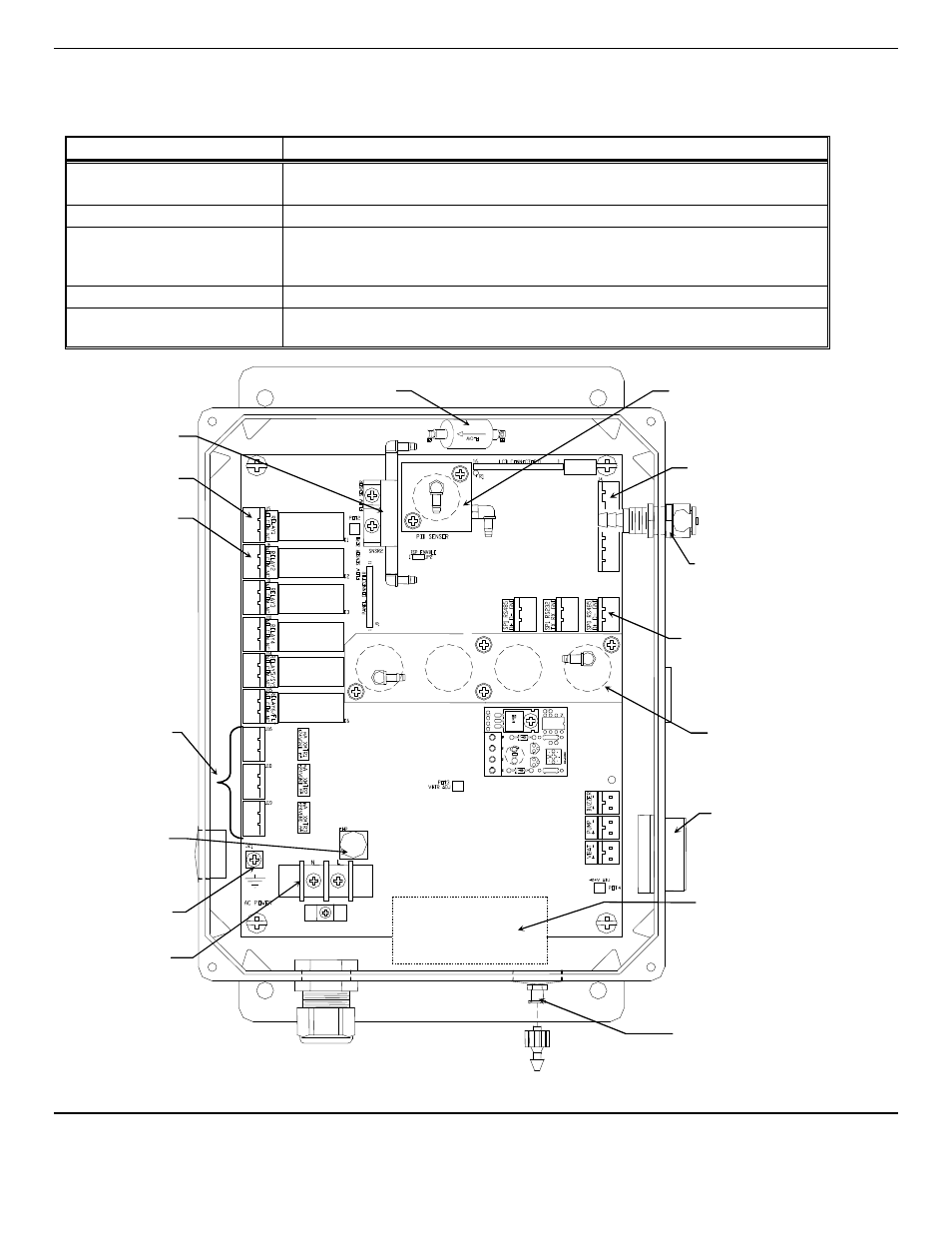
2.3 Circuit Board Features
The Display Panel is hinged on the left and is released by unscrewing the 2 screws located in the right corners. After releasing
the panel, it is swung to the left, exposing the interior of the enclosure. The Circuit Board is mounted at the back surface of the
enclosure interior. Features are shown in Figure 2.
Feature
Description
Relay Terminals
This group of terminals is located at the left side of the Circuit Board.
For the contacts for each of four alarm relays, and for the contacts of a fault relay.
Output Terminals
One 4-20mA output per active channel. 2 channels/outputs per connector.
HC Manifold
Sensor Manifold
The PiD sensor is installed into this housing.
The sample manifold, the carbon monoxide, carbon dioxide and oxygen sensors are
located under this housing.
Filter, Particulate
Removes contaminate from air sample line.
Sensor Terminals
J16, J18, J19
Sensor/Transmitter connectors 24
V
DC
4-20mA Input
Figure 2: GSM-60
Interior Features
Power Input
Terminal J23
Audio Alarm
Sensor PiD (HC)
Manifold
Relay Terminals
(6 places)
Sensor/Transmitter
Terminals
J16, J18, J19
Horn Terminal
Fuse Holders
1.0 Amp
Flow Sensor
Sensor
Manifold
Digital Communication
Terminals
Ground Screw
J21
Input Port Fitting
4 – 20mA Output
Terminals
4 places
Sampling Pump
Location
Particulate Filter
Output Port Fitting