Oscillator parts identification, Assemble the following components to the pc board – Elenco DataCom Tester Kit User Manual
Page 9
PARTS LIST - SECTION B
RESISTORS
Qty.
Symbol
Description
Color Code
Part #
r 1
R13
18kΩ 5% 1/4W
brown-gray-orange-gold
151800
r 1
R14
100kΩ 5% 1/4W
brown-black-yellow-gold
161000
CAPACITORS
Qty.
Symbol
Value
Description
Part #
r 1
C3
1µF
Electrolytic Radial
261047
SEMICONDUCTORS
Qty.
Symbol
Value
Description
Part #
r 1
U5
555
Integrated Circuit (IC) 555 Timer
330555
MISCELLANEOUS
Qty.
Symbol
Description
Part #
r 1
U5
Socket IC 8-pin
664008
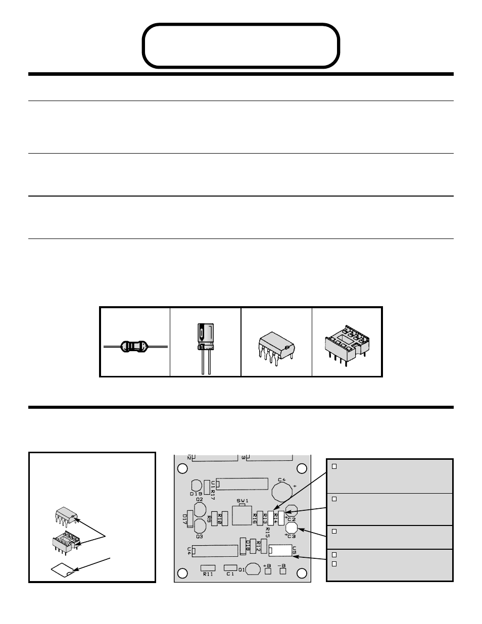
SECTION B
Oscillator
PARTS IDENTIFICATION
-8-
Resistor
Integrated Circuit (IC)
Electrolytic
IC Socket 8-pin
Figure I
Insert the IC socket into the PC board with the
notch in the direction shown on the top
legend. Solder the IC socket into place.
Insert the IC into the socket with the notch in
the same direction as the notch on the socket.
ASSEMBLE THE FOLLOWING COMPONENTS TO THE PC BOARD
In all of the following steps the components must be installed on the top legend side of the PC board. The
board is turned to solder the component leads on the foil side.
R13 - 18kΩ 5% 1/4W Resistor
(brown-gray-orange-gold)
(see Figure A)
R14 - 100kΩ 5% 1/4W Resistor
(brown-black-yellow-gold)
(see Figure A)
C3 - 1µF Electrolytic Radial
(see Figure G)
U5 - 8-pin IC Socket
U5 - 555 IC Timer
(see Figure I)
Notch
Notch
Marking