Elenco DataCom Tester Kit User Manual
Page 25
-24-
Configuration
for Testing
Communication
Cable
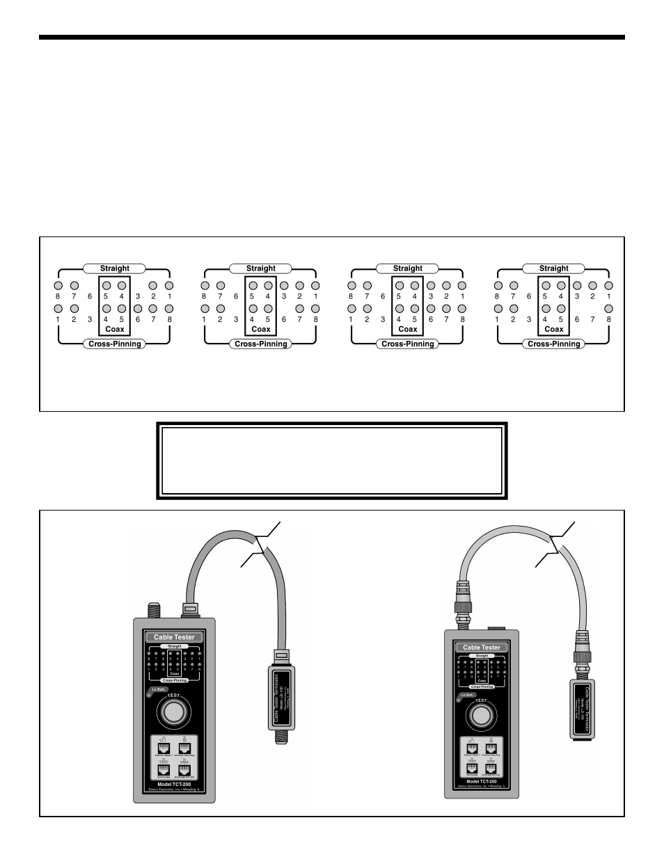
Configuration
for Testing
Coaxial Cable
1. Connect one end of the cable to be tested to the
terminator and the other end to the cable tester
as shown in Figure 17.
2. Push the TEST (power) button and read the result.
Good Pair: Two vertical and one single blinking
LEDs. The location of the single LED indicates a
straight or cross-pinning for the pair.
Open Pair: Only two vertical LEDs blinking.
Short: Four or more LEDs are blinking (two or
more wires are shorted).
3. Push the TEST button again and read the result
for the next pair.
4. For testing coax cable, use the middle LEDs (boxed
in as coax on the unit).
5. If you do not push the button for 30 seconds, it will
automatically shut off.
CAUTION
DO NOT test cable connected to electric power. To avoid electric
shock, disconnect the power to the cable under test. Connection to
an active power cable can result in injury or even death.
*
*
*
*
*
*
*
*
*
Open Pair
For straight open wire #3
For Cross-Pinning
open wire #6
Short
Cross-Pinned cable
short wires 6 & 7
*
= Blinking LED
*
*
*
Good Pair (Cross-Pinning)
3 & 6 Wires
Good Pair (Straight)
3 & 6 Wires
OPERATION INSTRUCTIONS
Figure 17