103k, Assemble components to the pc board, Identifying resistor values – Elenco Soldering Station User Manual
Page 9: Identifying capacitor values, Figure c, Figure a, Figure b, Bands, 100v
-8-
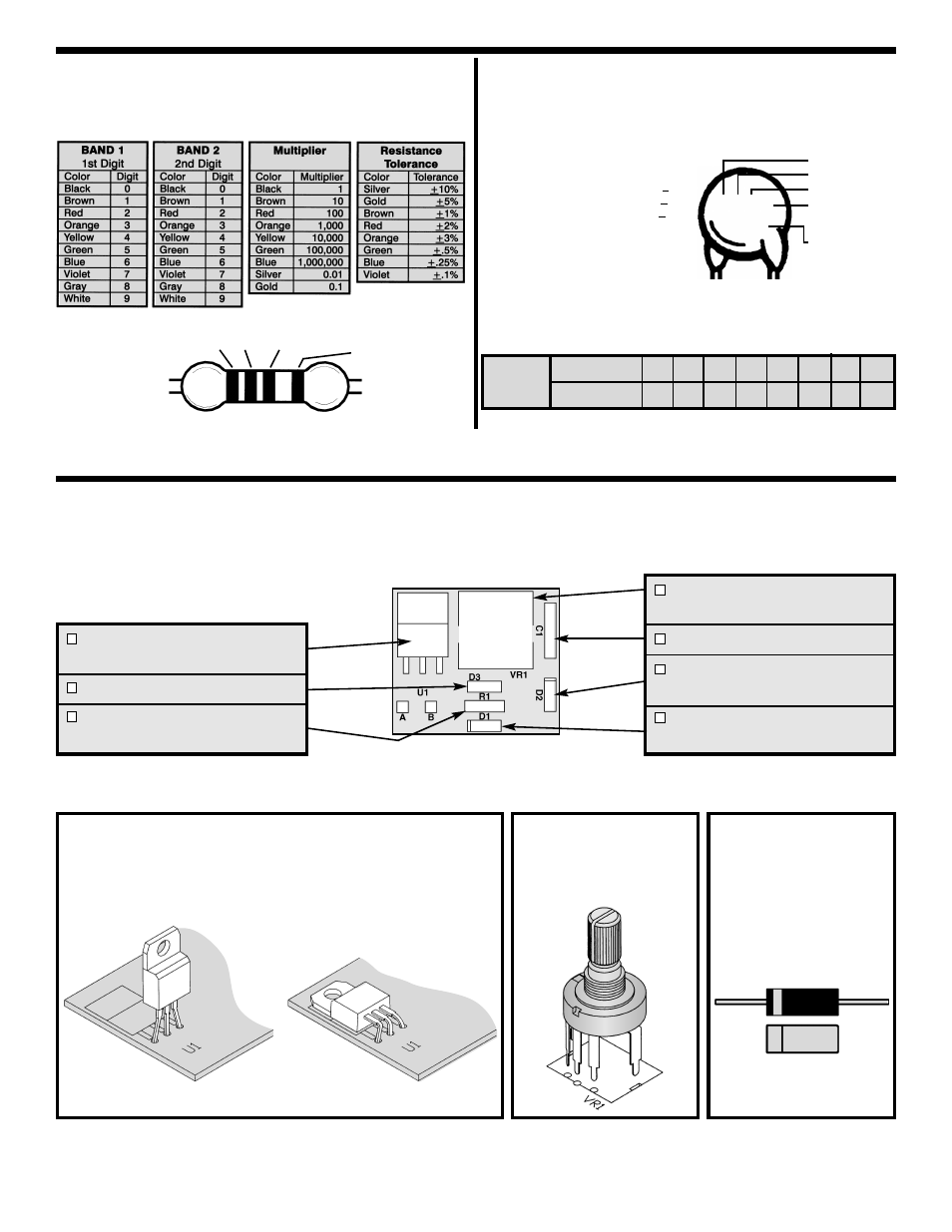
ASSEMBLE COMPONENTS TO THE PC BOARD
Care must be given to identifying the proper components and in good soldering habits. Place a check mark in
the box after each step is complete.
VR1 - 250k
Ω Potentiometer
(see Figure B)
C1 - .082
μF 200V Capacitor
D2 - 1N4004 Diode
(see Figure C)
D1 - 1N4004 Diode
(see Figure C)
Figure C
Diodes have polarity.
Mount them with the
band in the correct
direction, as marked on
the PC board.
Figure A
Mount the triac as shown. Bend the triac 90
O
. Solder and cut
off excess leads.
Figure B
Mount the potentiometer
as shown. Solder and
cut off excess leads.
TR1 - Triac BTA12400B
(see Figure A)
D3 - Diac DB3
R1 - 15k
Ω 5% 1/4W Resistor
(brown-green-orange-gold)
IDENTIFYING RESISTOR VALUES
Use the following information as a guide in properly identifying the
value of resistors.
IDENTIFYING CAPACITOR VALUES
Capacitors will be identified by their capacitance value in pF
(picofarads), nF (nanofarads), or
μF (microfarads). Most capacitors
will have their actual value printed on them. Some capacitors may
have their value printed in the following manner.
For the No.
0
1
2
3
4
5
8
9
Multiply By
1
10 100 1k 10k 100k .01 0.1
Multiplier
1
2
Multiplier
Tolerance
BANDS
Second Digit
First Digit
Multiplier
Tolerance
103K
100V
Maximum
Working Voltage
The value is 10 x 1,000 = 10,000pF or
.01
μF 100V
The letter M indicates a tolerance of +20%
The letter K indicates a tolerance of +10%
The letter J indicates a tolerance of +5%
Note:
The letter “R” may be used at times
to signify a decimal point; as in 3R3 = 3.3