Assemble components to the pc board – Elenco 100kHz Function Generator in Kit Form User Manual
Page 6
-5-
Figure B
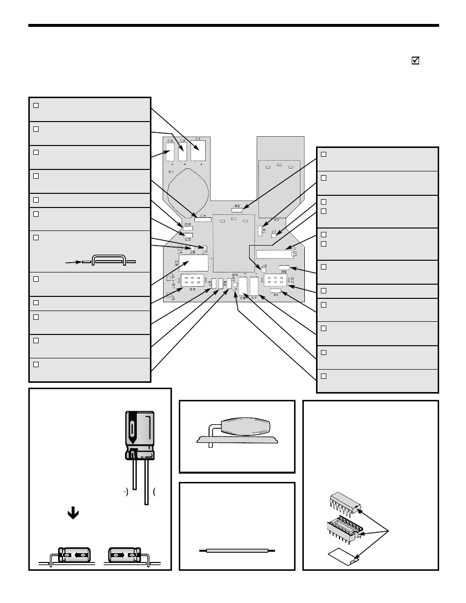
Bend the capacitor over before
soldering.
ASSEMBLE COMPONENTS TO THE PC BOARD
Care must be given to identifying the proper components and in good soldering habits. Refer to the soldering
tips section in this manual before you begin installing the components. Place a check mark in the box after
each step is complete.
Figure A
Electrolytic
capacitors
have polarity. Be sure to
mount them with the
short negative (–) lead
(marked on side) in the
correct hole.
Warning:
If the capa-
citor is connected with
incorrect polarity, it may
heat up and either leak or
cause the capacitor to
explode.
Mount the electrolytics horizontal to the PC
board. Bend the leads at right angles and
then insert the leads into the PC board.
Figure D
Insert the IC socket into the PC board
with the notch in the direction shown
on the top legend. Solder the IC
socket into place. Insert the IC into
the socket with the notch in the same
direction as the notch on the socket.
Notch
C1 - 100µF 16V Electrolytic
(see Figure A)
C2 - 10µF 16V Electrolytic
(see Figure A)
C3 - 1µF 50V Electrolytic
(see Figure A)
C4 - .1µF 10% Mylar (104)
(see Figure B)
C6 - 820pF 10% Discap (821)
C5 - .01µF 10% Mylar (103)
(see Figure B)
J7, J8 - Jumper wire
(use a discarded lead)
C9 - 1000µF 16V Electrolytic
(see Figure A)
S3 - Slide Switch DPDT
R7 - 8.2kΩ 5% ¼W Resistor
(gray-red-red-gold)
R8 - 10kΩ 5% ¼W Resistor
(brown-black-orange-gold)
R5 - 3.9kΩ 5% ¼W Resistor
(orange-white-red-gold)
R9 - 100kΩ 5% ¼W Resistor
(brown-black-yellow-gold)
R1 - 620Ω 5% ¼W Resistor
(blue-red-brown-gold)
J1 - 4” Black wire 22ga.
J3 - 2½” Black wire 22ga.
(see Figure C)
U1 - 16-pin IC socket
U1 - XR-2206 IC
(see Figure D)
R6 - 200Ω 5% ¼W Resistor
(red-black-brown-gold)
S2 - Slide Switch DPDT
R4 - 22kΩ 5% ¼W Resistor
(red-red-orange-gold)
C7 - 10µF 16V Electrolytic
(see Figure A)
C8 - 10µF 16V Electrolytic
(see Figure A)
J2 - 2½” Black wire 22ga.
(see Figure C)
(+)
(–)
or
Figure C
Cut one 4” and two 2½” wires
and strip ¼” of insulation off of
both ends of the wires. Solder
these wires to the points J1, J2,
and J3.
PC board