Testing the fg-500 function generator, Final assembly (continued) – Elenco 100kHz Function Generator in Kit Form User Manual
Page 10
-9-
r Remove the backing from each rubber foot and
place them in the locations shown in Figure M.
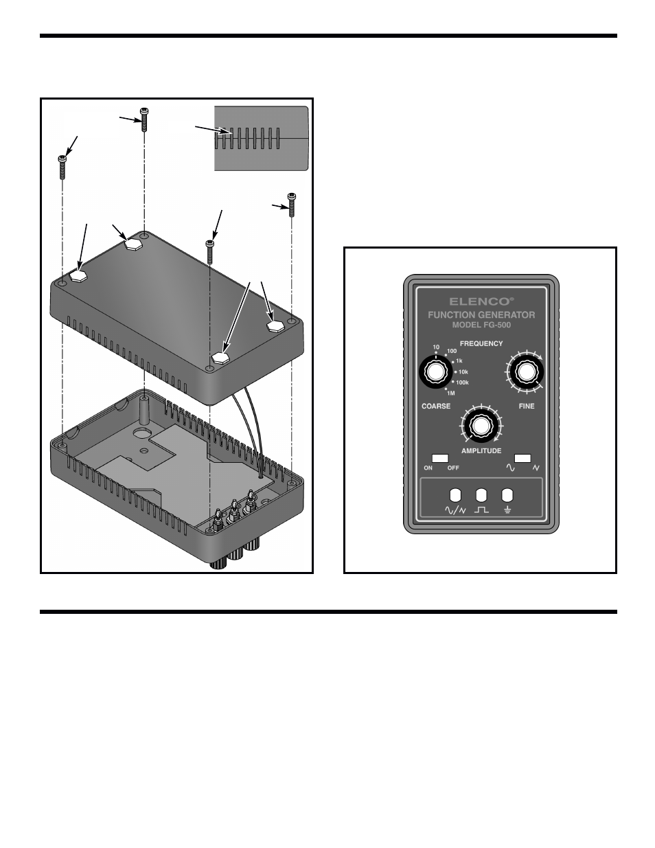
r Assemble the top and bottom case sections and
fasten with four 2.8 x 8mm self-tapping screws as
shown in Figure M. Make sure the slots on the
side line up with one another.
r Turn the shafts on the two potentiometers and
rotary switch fully counter-clockwise. Push the
three knobs onto the shafts so that the line on the
knobs are on the points shown in Figure N.
TESTING THE FG-500 FUNCTION GENERATOR
The unit may be tested by following the 4 steps listed below. Should any of these tests fail, refer to the
Troubleshooting Guide.
1) SET THE SWITCHES AND POTS AS FOLLOWS:
On/Off
On
Range
10
Frequency
Maximum (clockwise)
Amplitude
Maximum (clockwise)
Sine/Triangle
Set Sine/Triangle switch to Sine position
Figure M
2.8 x 8mm Screws
2.8 x 8mm
Screws
Rubber feet
Rubber
feet
Slot
Figure N
FINAL ASSEMBLY (continued)
- SEE AMFM108CK (56 pages)
- Computer Inteface for Snap Circuits® (60 pages)
- Capacitor Substitution Box (8 pages)
- Diode/Transistor Tester Kit (12 pages)
- Diode/Transistor Tester (8 pages)
- Electronic Component Kit (28 pages)
- 100kHz Function Generator (8 pages)
- Surface Mount Generator Kit (16 pages)
- 5MHz Function Generator (12 pages)
- 015V Power Supply Kit (8 pages)
- Resistor Substitution Box (8 pages)
- 3 3/4 Digit Cap./Ind./Logic (2 pages)
- Logic Probe Kit (12 pages)
- Logic Pulser Kit (12 pages)
- Compact Digital Multimeter (20 pages)
- Digital Multimeter (18 pages)
- 3 1/2 Digit Cap. / Trans. Kit (36 pages)
- Compact Multimeter (8 pages)
- Digital Mulitmeter Kit (20 pages)
- 23 Range 20k/V VOM in Kit Form (20 pages)
- 3 1/2 Digit Cap./ Freq./ Trans. w/ Grey Boot (8 pages)
- 3 1/2 Digit with Temperature (36 pages)
- 3 1/2 Digit Cap./ Trans./ Freq (4 pages)
- Digital Bench Multimeter (26 pages)
- MicroMaster ® Computer Training Kit (116 pages)
- 100MHz Scope (68 pages)
- Wide Band RF Generator (7 pages)
- Deluxe Solar Educational Kit (15 pages)
- Soldering Station (4 pages)
- Soldering Station (6 pages)
- Soldering Station (20 pages)
- Surface Mount Technology Kit (12 pages)
- Practical Soldering Project Kit (16 pages)
- DataCom Tester Kit (28 pages)
- MultiModular Cable Tester (4 pages)
- Tone Generator (4 pages)
- Telephone Line Analyzer Kit (16 pages)
- Digital / Analog Trainer Kit Version (52 pages)
- Digital / Analog Trainer in Case (16 pages)
- Deluxe Digital / Analog Trainer with Tools Kit Version (52 pages)
- Digital / Analog Trainer (12 pages)
- Deluxe Digital / Analog Trainer (16 pages)
- Variable Voltage Power Supply Kit (12 pages)
- Variable Voltage Power Supply (8 pages)