Introduction identifying capacitor values, Identifying resistor values, Specifications – Elenco 100kHz Function Generator in Kit Form User Manual
Page 4
-3-
INTRODUCTION
IDENTIFYING CAPACITOR VALUES
Capacitors will be identified by their capacitance value in pF (picofarads), nF (nanofarads) or µF (microfarads). Most
capacitors will have their actual value printed on them. Some capacitors may have their value printed in the following manner.
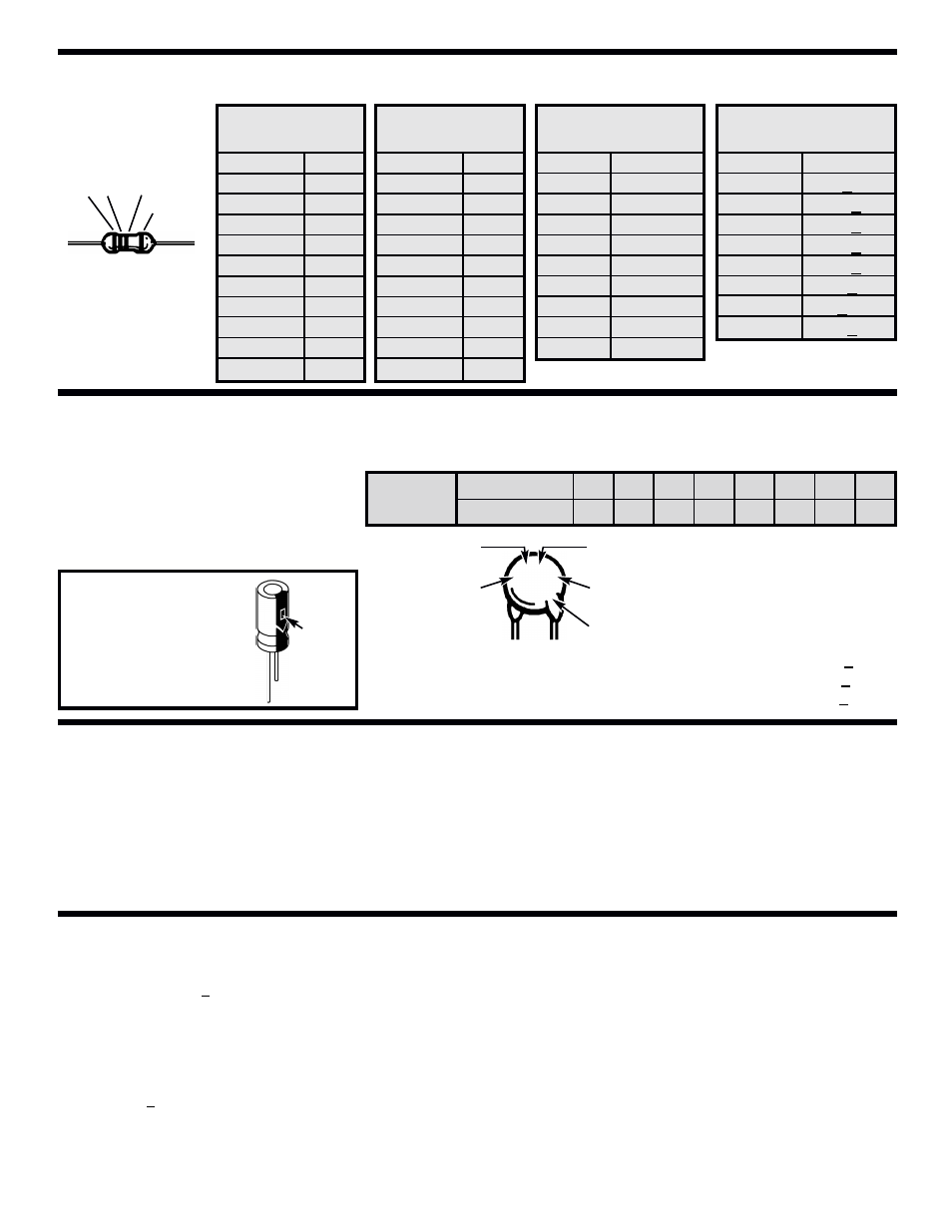
IDENTIFYING RESISTOR VALUES
Use the following information as a guide in properly identifying the value of resistors.
BAND 1
1st Digit
Color
Digit
Black
0
Brown
1
Red
2
Orange
3
Yellow
4
Green
5
Blue
6
Violet
7
Gray
8
White
9
BAND 2
2nd Digit
Color
Digit
Black
0
Brown
1
Red
2
Orange
3
Yellow
4
Green
5
Blue
6
Violet
7
Gray
8
White
9
Multiplier
Color
Multiplier
Black
1
Brown
10
Red
100
Orange
1,000
Yellow
10,000
Green
100,000
Blue
1,000,000
Silver
0.01
Gold
0.1
Resistance
Tolerance
Color
Tolerance
Silver
+10%
Gold
+5%
Brown
+1%
Red
+2%
Orange
+3%
Green
+.5%
Blue
+.25%
Violet
+.1%
Bands
1
2
Multiplier
Tolerance
Electrolytic capacitors have a positive and a
negative electrode. The negative lead is
indicated on the packaging by a stripe with
minus signs and possibly arrowheads. Also, the
negative lead of a radial electrolytic is shorter
than the positive one.
Warning:
If the capacitor is connected
with incorrect polarity, it may
heat up and either leak, or
cause the capacitor to
explode.
OUTPUT:
• Waveforms: Sine, Triangle, Square
• Impedance: 600Ω + 10%.
• Frequency: 1Hz - 1MHz in 6 decade steps with variable
ranges.
SINE WAVE:
• Amplitude: 0 - 3Vpp
• Distortion: Less than 1% (at 1kHz)
• Flatness: +0.05dB 1Hz - 100kHz
SQUARE WAVE:
• Amplitude: 8V (no load)
• Rise time: Less than 50ns (at 1kHz)
• Fall time: Less than 30ns (at 1kHz)
• Symmetry: Less than 5% (at 1kHz)
TRIANGLE WAVE:
• Amplitude: 0 - 3Vpp
• Linearity: Less than 1% (up to 100kHz)
POWER REQUIREMENTS:
• Standard 9V battery
OPERATING TEMPERATURE:
• 0
O
C to 50
O
C
Polarity
marking
(+)
(–)
Multiplier
For the No.
0
1
2
3
4
5
8
9
Multiply By
1
10
100
1k
10k 100k .01
0.1
Second digit
First digit
Multiplier
Tolerance*
Note: The letter “R” may be
used at times to signify a
decimal point; as in 3R3 = 3.3
103K
100V
The letter M indicates a tolerance of +20%
The letter K indicates a tolerance of +10%
The letter J indicates a tolerance of +5%
Maximum working voltage
The value is 10 x 1,000 =
10,000pF or .01µF 100V
*
Assembly of your FG-500 Function Generator will
prove to be an exciting project and give much
satisfication and personal achievement. The FG-500
contains a complete function generator capable of
producing sine, square and triangle wave forms. The
frequency of this generator can be contiuously varied
from 1Hz to 1MHz in 6 steps. A fine frequency control
makes selection of any frequency in between easy.
The amplitude of the wave forms are adjustable from
0 to 3Vpp. This complete function generator system
is suitable for experimentation and applications by
the student. The entire function generator is
comprised of a single XR-2206 monolithic IC and a
limited number of passive circuit components.
SPECIFICATIONS