Project #pc71 space war alarm combo pc, Project #pc70 – Elenco Computer Inteface for Snap Circuits® User Manual
Page 58
-57-
Build the circuit and press the press switch a few times, you hear
cute sounds like a bumble bee. Use Winscope to see how the
waveform fades away after you release the switch, and try storage
mode as shown here.
You may replace the 0.02mF capacitor C1 with 0.1mF
capacitor C2
or 10mF
capacitor C3 (“+” on the right) to change the sound, but
you may want to change the time scale.
You may also replace the 100mF capacitor C4 with the 10mF
capacitor C3 or the 470mF
capacitor C5 to change the duration of
the sound.
Settings
Time scale
Storage mode
Project #PC70
Remove the speaker from the circuit and place the whistle chip
(WC) across the transformer at points labeled A &
B on the circuit
layout, connect the PC-interface cable across the whistle chip.
Listen to the sounds and view the waveforms as you press the
press switch. Replace the 0.02mF capacitor C1 with 0.1mF
capacitor C2 or 10mF
capacitor C3 (“+” on the right) to change the
sound, or replace the 100mF capacitor C4 with the 10mF capacitor
C3 (“+” on the right) or the 470mF
capacitor C5 to change the
duration.
Bee PC (II)
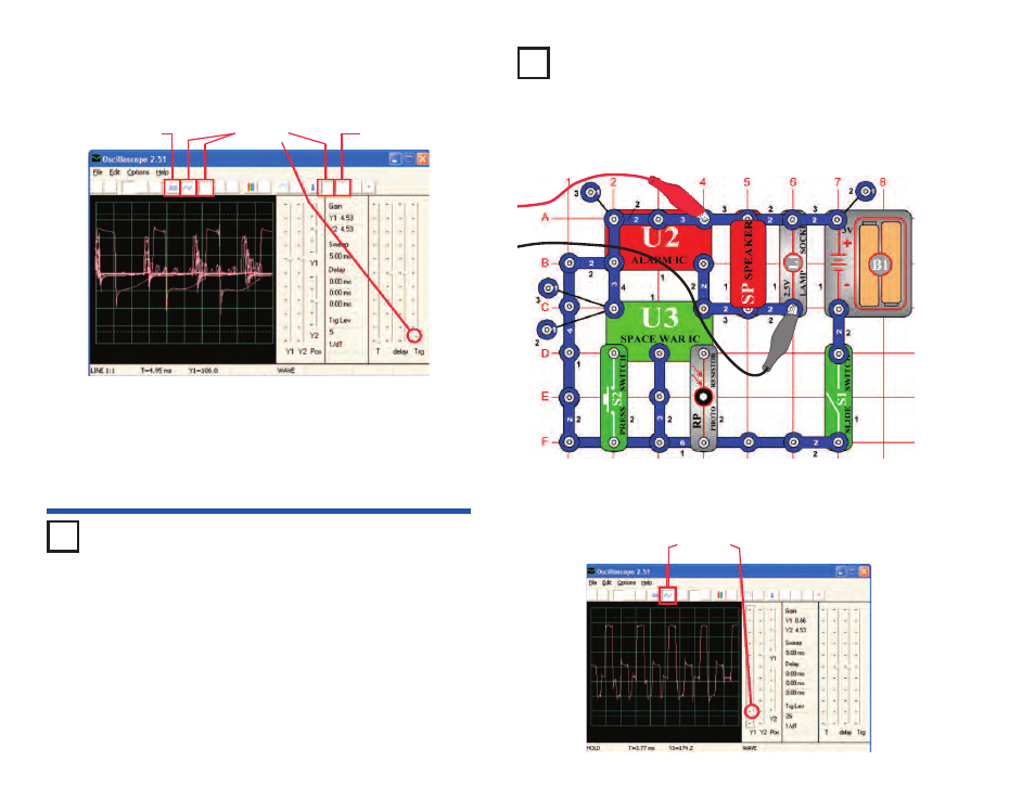
Build the circuit and try the settings shown. Turn it on, press the
press switch (S2) several times, and wave your hand over the
photoresistor (RP) to view all the sound combinations. You may
also use FFT mode to view the frequency spectrum.
Project #PC71
Space War Alarm Combo PC
OBJECTIVE: To view the output of the combined outputs from
the space war and alarm integrated circuits.
Settings