Elenco Computer Inteface for Snap Circuits® User Manual
Page 3
-2-
Electronic engineers use specialized test equipment to “see”
electronic signals and make performance measurements. They
use an oscilloscope to look at the shape of the signal and use a
spectrum analyzer to look at its frequency content. This
equipment is specialized and usually very expensive.
The Winscope software simulates this equipment using your
personal computer. The PC-interface cable can be connected
across any 2 points in your circuit to look at the signal.
It is usually connected to the output of a circuit, as in the circuits
shown for the CI-73.
Connect the plug end of the probe to the
microphone input on your personal computer.
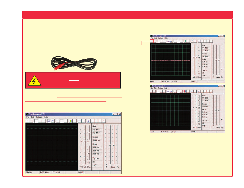
Run the
Winscope application (Winscope.exe). It will come up in Hold
mode looking like this:
Click on the On-Line button to turn it on. You should now get
one of the following 2 pictures, depending on whether your
microphone input is properly turned on:
If you get the picture shown in Example B, then your microphone
input is not properly turned on. Go to the “Turning On Your
Microphone Input” section to turn it on. There may also be other
sound card controls on your computer that you need to set.
When your input is properly configured, you will get a picture like
Example A above. Touch the red and black “alligator” clips on the
PC-interface cable to each other and you should see the random
pattern on the Winscope screen change as you do so. You are
now ready to proceed with the first CI-73 experiment or you may
investigate the Winscope software on your own.
Looking at Electronic Signals using the WINSCOPE Software
WARNING:
SHOCK HAZARD - NEVER connect the probe to AC
power
or a wall electricity outlet for any reason since serious injury
or damage may result.
Example
A
Example
B
On-Line
button