Project #pc55 electronic cat pc, Project #pc54, Project #pc56 – Elenco Computer Inteface for Snap Circuits® User Manual
Page 52: Project #pc57, Project #pc58
-51-
Project #PC54
Bird Sounds PC (II)
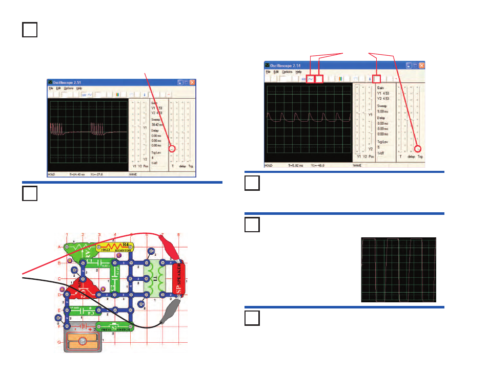
Replace the 100mF capacitor (C4) with the 10mF capacitor (C3). The
frequency of the oscillator is the same as before (and so the pulses look
the same), but the oscillator activates in shorter intervals (so the bursts of
pulses are shorter but closer together). You could use the 470mF
capacitor to increase the oscillation interval.
Project #PC55
Electronic Cat PC
OBJECTIVE: To view the output of an oscillator circuit.
Build the circuit and try the settings shown. Start with the
adjustable resistor set to the left but then adjust to change the
tone. The signal dies out after you release the switch.
Settings
Project #PC56
Connect the whistle chip across points A &
B, then B
&
C, then C
&
D and
observe how the waveform changes as the sound changes.
Project #PC57
Remove the speaker. Connect the PC
interface cable across the whistle chip
and install the whistle chip across
points A &
B, then B
&
C, then C
&
D
and observe how the waveform
changes as the sound changes. Try
different settings of the adjustable
resistor. The waveform for B
& C
is
shown.
Electronic Cat
PC (III)
Electronic Cat
PC (II)
Project #PC58
Replace the 100mF
capacitor with the 470mF
capacitor and repeat projects PC55-
PC57. The signal dies out at a much slower rate now, making it easier to observe.
You can also use FFT mode to view the frequency spectrum as desired.
Electronic Cat
PC (IV)