Elenco Computer Inteface for Snap Circuits® User Manual
Page 11
-10-
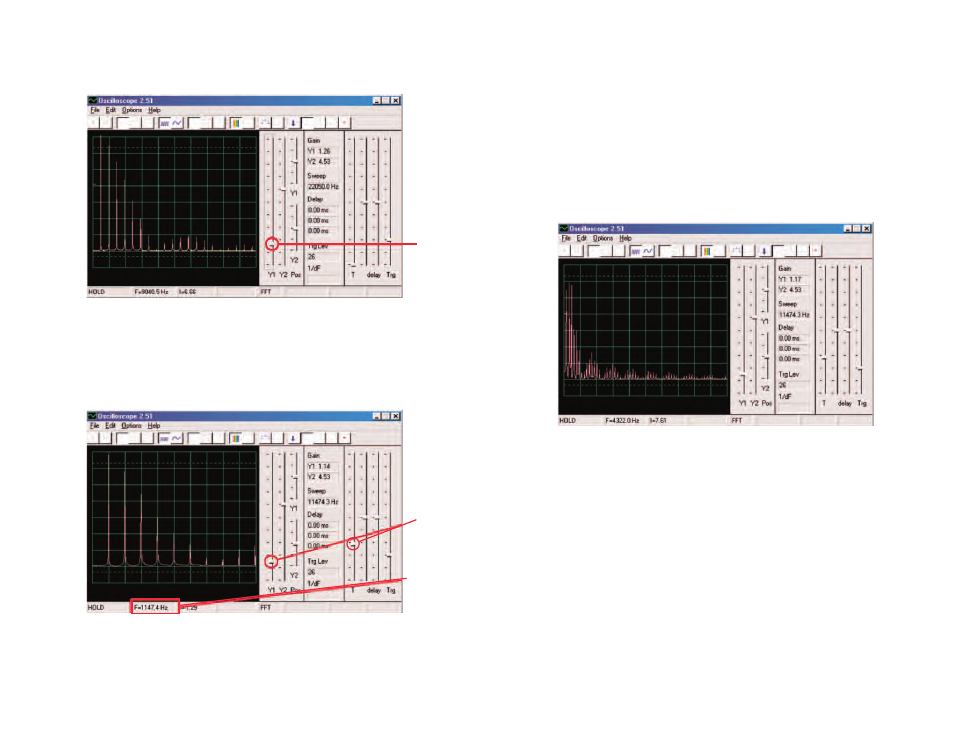
The 1:1 gain mode does not apply to the FFT
screen, so move the
Y1 gain control down to here so you can see the peak energy at
the low frequencies.
Move the adjustable resistor control (snap part RV) and watch how
it changes the frequencies on the display.
Set the adjustable resistor control (snap part RV) to mid-range. In
addition to the 5ms/div and 0.5ms/div settings for the horizontal
scale, there is also a variable setting. See if you can set it so that
all the signal peaks line up with the grid lines, as shown.
Y1 gain
control
level
Variable
setting
As you can see, all the peaks are equally spaced in frequency.
Move your computer mouse directly over the first peak, the
software displays the frequency you are pointing at. Move the
mouse to the other peaks and you see they are multiples of the first
frequency.
Frequency
Now you can see that the tone you hear is actually a range of
related frequencies combined together. The first peak is considered
to be the main signal (and it is usually but not always the highest),
the energy at all the other peaks determine the waveform of the
signal you see on an oscilloscope.
Now modify your circuit by placing the 0.1mF capacitor (C2) on top
of the 0.02mF capacitor (C1).
By increasing circuit capacitance, you lower the oscillation
frequency and your display should now look something like this: