Operational amplifiers / filters, Field of view, Circuit description (see page 16) – Elenco Motion Detector Kit User Manual
Page 7: Figure 4, Figure 5, Figure 6 figure 7, And –v
This causes a change in current from the drain to
source. Very little power is required at the gate to
control the larger current flow from source to drain.
The benefits of this type of detector are low radio
interference, low noise, specially suited response.
The IR detector is sealed in a metal housing to
prevent electromagnetic interference and to keep
them clean.
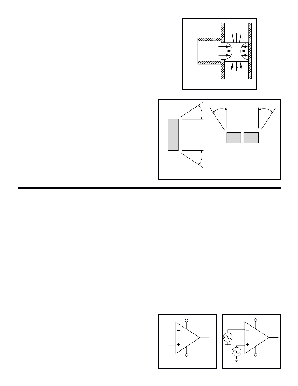
FIELD OF VIEW
Detectors are available with different fields of view,
depending on the application. The maximum
distance and total angle of view are important
specifications needed in choosing a motion detector.
The LHI-954 field of view is shown in Figure 5.
CIRCUIT DESCRIPTION (see page 16)
The IR Section contains only a few components,
R1, R2, C1 and the PIR sensor. As motion is
detected, the IR detector will produce a voltage at
the gate of the FET allowing current to flow from the
drain to source, causing the voltage at the input of
U1 (pin 13) to change, thus changing the output at
pin 14. Resistors R1 and R2 limit the amount of
current flow through the FET.
-6-
An amplifier is a device that uses a small amount
of power to control a larger amount of power. Just
like a small amount of power on the valve arm of
Figure 1 controlled the water pressure in the pipes
going to the houses. The amplifier does not create
power (it was already there in the water tower) but
it controls the power from a source.
In electronics, amplifiers are composed of devices
called transistors, resistors, and capacitors. The
number of these components used and the way
they are assembled determines the characteristics
of the amplifier. An amplifier that can perform many
mathematical operations such as adding,
subtracting, or multiplying voltages is called an
Operational Amplifier or Op-Amp.
The characteristics of an ideal op-amp are the
following:
A. infinite voltage gain (no voltage at all on the
input controls, large voltage on the output).
B. infinite bandwidth (no matter how fast the input
changes, the output will change just as fast).
C. infinite input impedance (no power required at
input to change output).
D. zero output impedance (the output can deliver
an infinite amount of power).
Obviously, in the real world these conditions can
never be met, but for mathematical purposes they
are assumed in designing electronic circuits with
op-amps.
The op-amp has two input terminals, inverting input
(–) and non-inverting input (+), and one output
terminal. Figure 6 shows the standard op-amp
symbol. The two input terminals are labeled 2 and 3,
and the output is 1. Most op-amps operate with two
DC power supplies, +V
CC
and –V
EE
connect to pins
11 and 4 respectively. Since a single power supply
is used in the kit, –V
EE
(pin 4) is tied to ground. The
op-amp multiplies the difference between the
voltage signals applied at its two input terminals
(V3-V2) times the gain of the amplifier (A). A x (V3-
V2) appears at the output terminal as shown in
Figure 7.
OPERATIONAL AMPLIFIERS / FILTERS
Figure 4
Gate
Drain
Source
FET Transistor
Horizontal
Figure 5
Vertical
56
O
56
O
46
O
46
O
Figure 6
Figure 7
Inverting
Input
Non-
Inverting
Input
2
3
4
11
1
Output
+Vcc
–V
EE
2
3
4
11
1
Output
A (V3 - V2)
+Vcc
–V
EE
V2
V3