Elenco Motion Detector Kit User Manual
Page 15
-14-
4. Measure the voltages at IC1 when activated.
A. Incorrect voltage readings:
1. Check resistors R3 - R12 for correct value.
2. Check diode D1 polarity.
3. Check C3 and C4 polarity.
4. IC1 may be defective.
SOUND GENERATOR
Measure the voltage at the following pins on U2, as listed in the chart below.
A. No voltage at pin 3:
1. Check R13, R14, SW1 and C5.
B. No 5V at pin 5:
1. Check SW1 solder connection.
2. No 5V at pin 6.
3. Check C9.
C. Outputs two short tones:
1. Check C5.
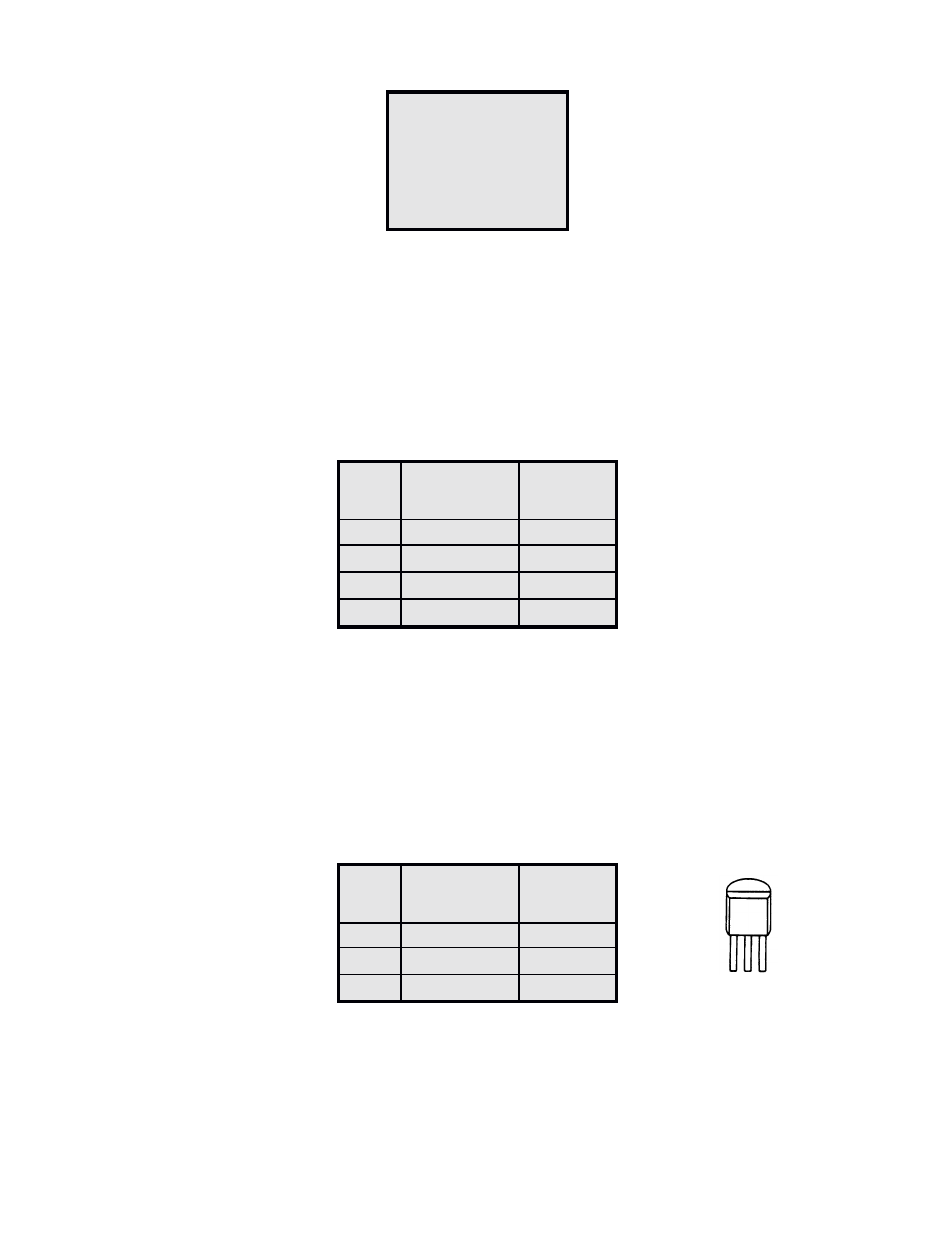
Pin
Voltage
1
0 - 3.8V
7
0 - 3.8V
8
0 - 3.8V
14
1.5 - 3.8V
U2
Voltage
Voltage
Pin
No Sound
Sound
3
0
0 - 4V
5
5V
5V
6
5V
7
0V
.735V
Q1
Voltage
Voltage
Pin
No Sound
Sound
E
0
0V
B
0V
.355V
C
9V
7 - 9V
Q1
E B C
See also other documents in the category Elenco Toys:
- Upgrade Kit SC100 to SC300 (76 pages)
- Snap Circuits Jr.® Educational 100 Exp. (48 pages)
- Upgrade Kit SC300 to SC500 (64 pages)
- Snap Rover ® (24 pages)
- XP&trade (64 pages)
- Snap Circuits LIGHT ® (84 pages)
- Snap Circuits Extreme® Educational 750 Exp. (88 pages)
- Projects PC1-PC73 (60 pages)
- Electronics 202 (132 pages)
- Snaptricity® (92 pages)
- Upgrade Kit SCROV10 to SCROV50 (48 pages)
- Snap Circuits Green ® (80 pages)
- C Adapter for Snap Circuits® (2 pages)
- Digital Roulette Kit (16 pages)
- FM Wireless Microphone Kit (12 pages)
- AM Radio Kit (32 pages)
- AM Radio Kit (36 pages)
- AM/FM Radio Kit (64 pages)
- Circuit Maker Skill Builder 125 (64 pages)
- Circuit Maker Sound Plus 200 (80 pages)
- Understanding Logic Gates (16 pages)
- Understanding Logic Gates and Circuits (42 pages)
- Tumbling Robot (12 pages)
- Solar Energy (16 pages)
- C2D Scope (16 pages)
- 288x Astrolon Telescope with Aluminum Tripod (1 page)
- Simulated Frog Dissection Kit (1 page)
- Talking Galaxy Planetarium with Night Light (1 page)
- Night’n Day® (10 pages)
- Radio Controlled Black Widow (1 page)
- Handheld Microscope (2 pages)
- Water Filtration Kit (8 pages)
- 6-in-1 Solar Kit (18 pages)
- Microscope Set in Carrying Case (1 page)
- Mobile 20 Telescope (1 page)
- Mechanical Drum (20 pages)
- Aerial Screw (20 pages)
- Swing Bridge (20 pages)
- Printing Press (24 pages)
- MultiBarrel Cannon (20 pages)
- Armored Car (24 pages)
- Paddleboat (20 pages)
- SelfPropelled Cart (20 pages)
- Catapult (24 pages)