Assemble components (continued) – Elenco Motion Detector Kit User Manual
Page 11
-10-
ASSEMBLE COMPONENTS (CONTINUED)
+
Inside Pads
Outside Pads
Note: The text printed
on
the
LHI-954
Infrared Detector is
the date code.
Figure E
Use a discarded lead for
a jumper wire.
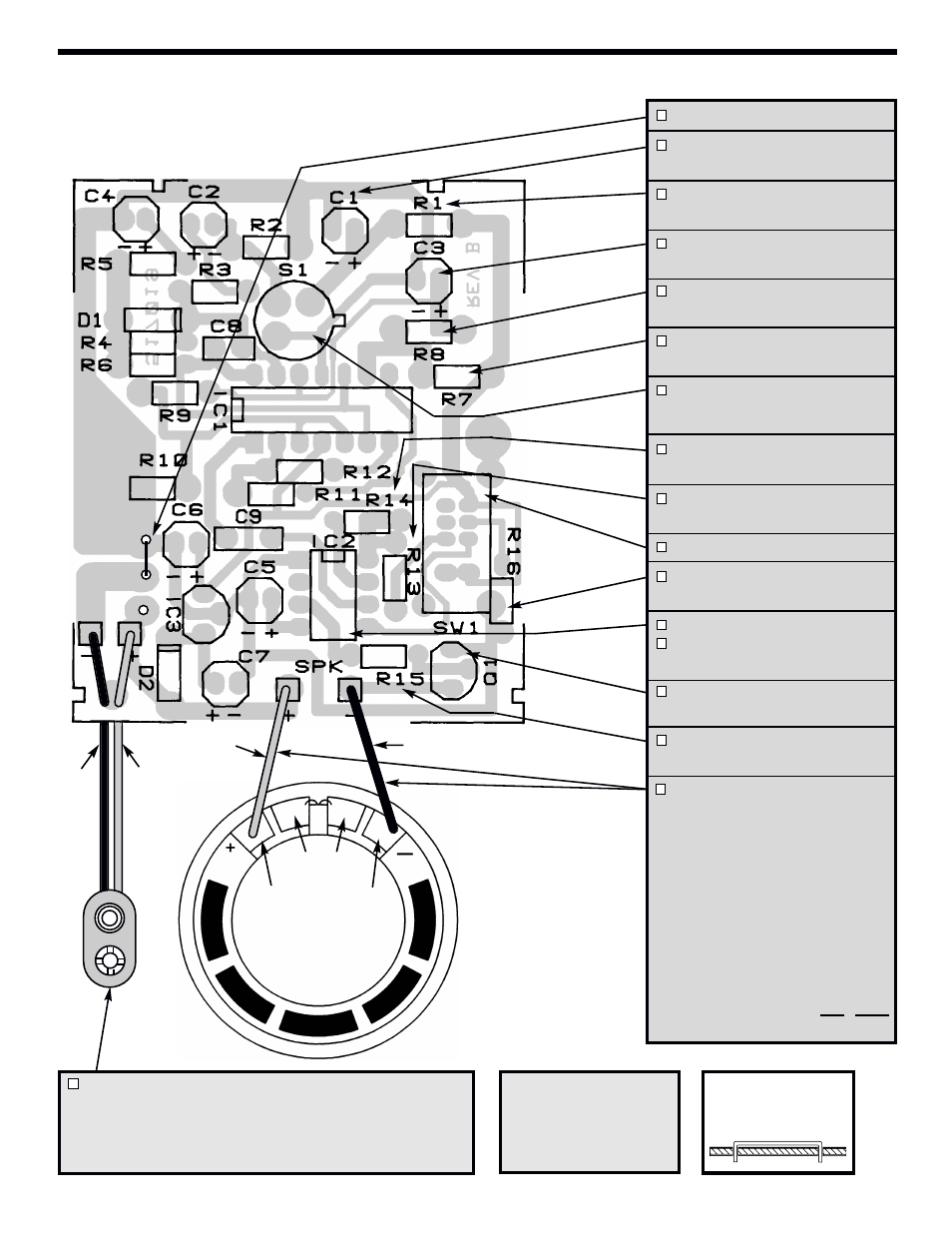
Jumper Wire (see Figure E)
C1 - 100µF 16V Electrolytic
(see Figure D)
R1 - 47kΩ 5% 1/4W Resistor
(yellow-violet-orange-gold)
C3 - 10µF 25V Electrolytic
(see Figure D)
R8 - 47kΩ 5% 1/4W Resistor
(yellow-violet-orange-gold)
R7 - 1.2MΩ 5% 1/4W Resistor
(brown-red-green-gold)
S1 - LHI-954 Infrared Detector
Mount with tab in the same direction as
marked on the PC board (see note below).
R14 - 270kΩ 5% 1/4W Res.
(red-violet-yellow-gold)
R13 - 470kΩ 5% 1/4W Resistor
(yellow-violet-yellow-gold)
SW1 - Slide Switch
R16 - 300Ω 5% 1/4W Resistor
(orange-black-brown-gold)
8-pin IC Socket
IC2 - HT2812G Integrated Circuit
(see Figure C)
Q1 - MPSA18 Transistor
(see Figure B)
R15 - 5.6kΩ 5% 1/4W Resistor
(green-blue-red-gold)
Speaker Wires - Solder the
two wires to the PC board
marked SPK +, –.
Note: If wires need resoldering;
1. First apply a small amount of
solder to the outside pad.
2. Solder the speaker wire to
the outside pads.
CAUTION: The internal
speaker wires are soldered to
the inside pads. DO NOT
unsolder these wires.
B1 - Battery Snap
Identify the battery snap B1. Insert the red and black wires
through the hole from the copper side of the PC board.
Insert the red wire into the (+) positive hole and the black
wire into the (–) negative hole as shown above.
Red
Black
–