Assemble components to the pc board – Elenco Motion Detector Kit User Manual
Page 10
-9-
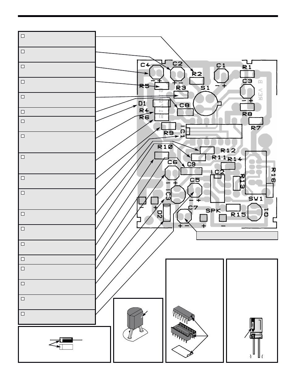
ASSEMBLE COMPONENTS TO THE PC BOARD
Note: C7 is not used in this kit.
Figure D
These
capacitors
are
polarized. Be sure to
mount them with the “+”
lead in the correct hole as
marked on the PC board.
Warning: If the capacitor
is connected with incorrect
polarity it may heat up and
either leak or cause the
capacitor to explode.
Figure B
Mount the device with the flat
side in the same direction as
shown on the PC board. Solder
and cut off the excess leads.
Figure C
Align the socket notch (if any)
with the notch marked on the
PC board.
Solder the socket to the PC
board. Insert the IC into the
socket with the notch as shown
below.
R2 - 47kΩ 5% 1/4W Resistor
(yellow-violet-orange-gold)
C2 - 10µF 25V Electrolytic
(see Figure D)
C4 - 22µF 25V Electrolytic
(see Figure D)
R5 - 39kΩ 5% 1/4W Resistor
(orange-white-orange-gold)
R3 - 75kΩ 5% 1/4W Resistor
(violet-green-orange-gold)
C8 - 470pF (471) Discap
D1 - 1N4148 Diode
(see Figure A)
R4 - 1.6MΩ 5% 1/4W Resistor
(brown-blue-green-gold)
(See Note)
R6 - 120kΩ 5% 1/4W Resistor
(brown-red-yellow-gold)
(See Note)
R9 - 47kΩ 5% 1/4W Resistor
(yellow-violet-orange-gold)
14-pin IC Socket
IC1 - LM324 Integrated Circuit
(see Figure C)
R12 - 300kΩ 5% 1/4W Resistor
(orange-black-yellow-gold)
R11 - 300kΩ 5% 1/4W Resistor
(orange-black-yellow-gold)
R10 - 510kΩ 5% 1/4W Resistor
(green-brown-yellow-gold)
C9 - .01µF (103) Discap
C6 - 100µF 16V Electrolytic
(see Figure D)
IC3 - 78L05 Integrated Circuit
(see Figure B)
D2 - Use a Jumper Wire in
place of the diode.
C5 - 22µF 25V Electrolytic
(see Figure D)
Figure A
Diodes have polarity. Be sure to mount them with the band
going in the same direction as marked on the PC board.
Band
Polarity
marking
(–)
(+)
Flat
Notch