Pulse meter inputs – Echelon SmartServer 2.2 Hardware User Manual
Page 27
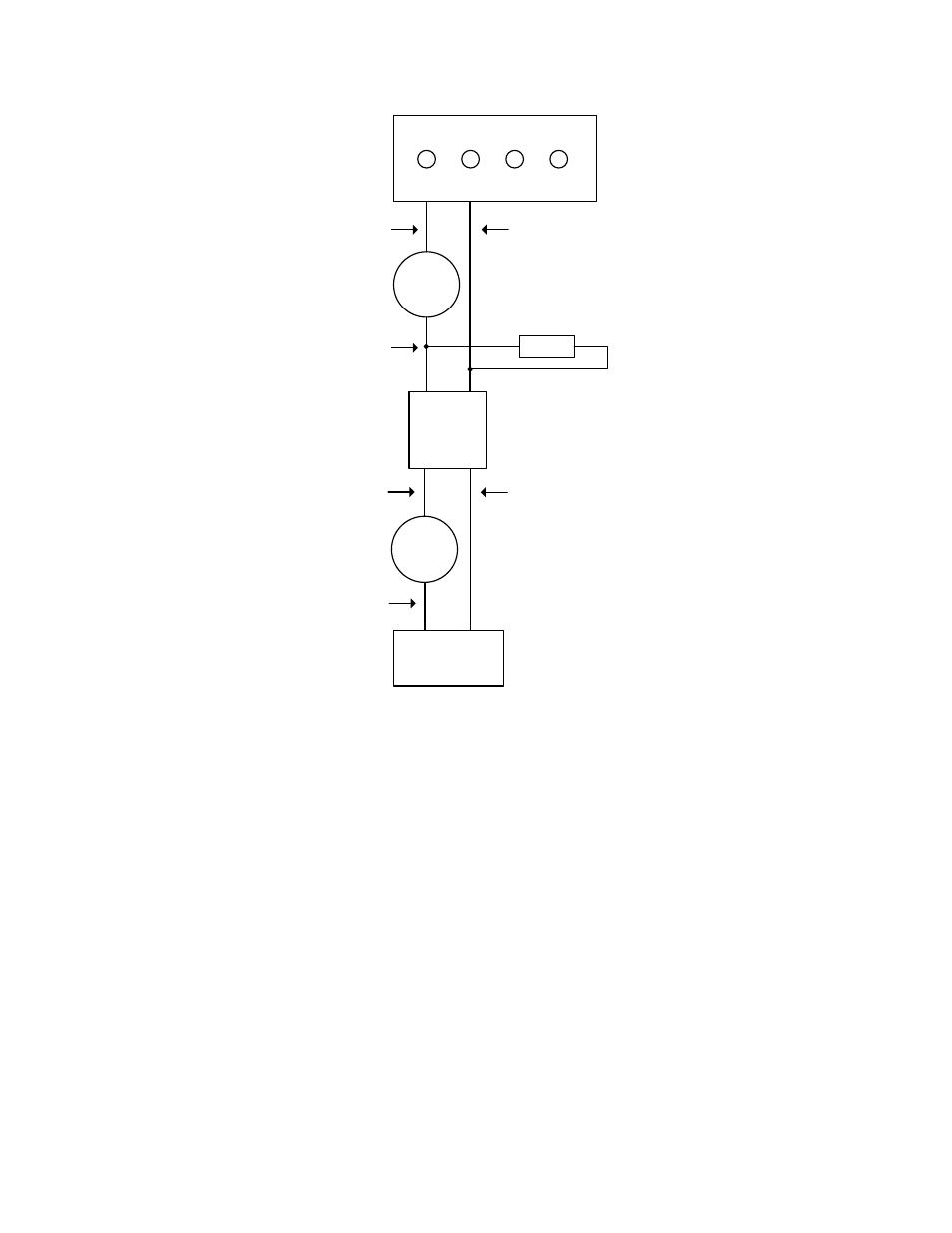
DC Voltage
Source
Inductive Load
DC +
DC -
Inductive Load
AC Line
AC Neutral
SSR
- Control +
Output
Load
Resistor
5
6
7
8
AC Voltage
Source
Switched AC Line
Switched DC +
Pulse Meter Inputs
The SmartServer includes two impulse meter inputs that comply with the DIN 43 864 impulse standard
(open terminal voltage <12VDC, maximum current
≤27mA). The pulse meter input connections are
implemented on screw terminals 9–12: Meter 2 is connected to terminals 9-10; Meter 1 is connected to
terminals 11-12. These connections are polarity-sensitive: terminals 9 and 11 are marked negative (-),
and terminals 10 and 12 are marked positive (+). You cannot reverse the polarity of the pulse meter
inputs because it will cause improper operation of the measurement circuits.
Each of the pulse meter inputs is controlled by a Pulse Counter application on the SmartServer. A
pulse input meter registers a pulse when the circuit between its positive and negative connections is
closed (the voltage is 0) for 30ms or longer. The circuit must be open for a minimum of 30ms between
pulses. See Chapter 9 of the SmartServer 2.2 User’s Guide for configuring the SmartServer to use the
pulse meter inputs to which it is connected.
The following figure illustrates the location of the pulse meter input screw terminals on the
SmartServer.
SmartServer 2.2 Hardware Guide
15