Digital outputs – Echelon SmartServer 2.2 Hardware User Manual
Page 25
and RS-485 serial ports, and use a custom driver for communication between the SmartServer and the
devices over the RS-232 or RS-485 serial interfaces.
You can create custom drivers for your SmartServer with Echelon SmartServer Programming Tools.
A demo version of the Echelon SmartServer Programming Tools is available on the SmartServer 2.2
DVD. To build custom drivers and deploy them on your SmartServer, order the Echelon SmartServer
Programming Tools DVD. To order this DVD, contact your Echelon sales representative.
In addition, a programmability license must be installed on the SmartServer to deploy custom drivers
on it. If a programmability license is not pre-installed on your SmartServer, you can order one
(Echelon model number 72161) from the Echelon or your Echelon product distributor.
For more information on creating custom drivers and deploying them on your SmartServer, see the
SmartServer 2.2 Programming Tools User’s Guide.
Digital Outputs
The SmartServer includes two high-voltage, high-current, single pole single throw (SPST) relay
outputs rated to switch resistive loads at 230VAC @ 10A or 24VDC @ 10A. For switching inductive
loads, see below. The relay connections are implemented on screw terminals 5-8: Output 1 is
connected to terminals 5-6; Output 2 is connected to terminals 7-8. The SPST relay contacts are
polarity-insensitive, and they can be used to switch both AC and DC loads. The relays require a
minimum load of 5V at 100mA in order to avoid low-voltage contact pitting, and therefore require a
parallel load resistor to switch TTL level signals.
Each of the relay outputs is controlled by a Digital Output application on the SmartServer. The relays
can be triggered by the Digital Output applications or by the receipt of remote messages. See Chapter
9 of the SmartServer 2.2 User’s Guide for configuring the SmartServer to use the digital outputs to
which it is connected.
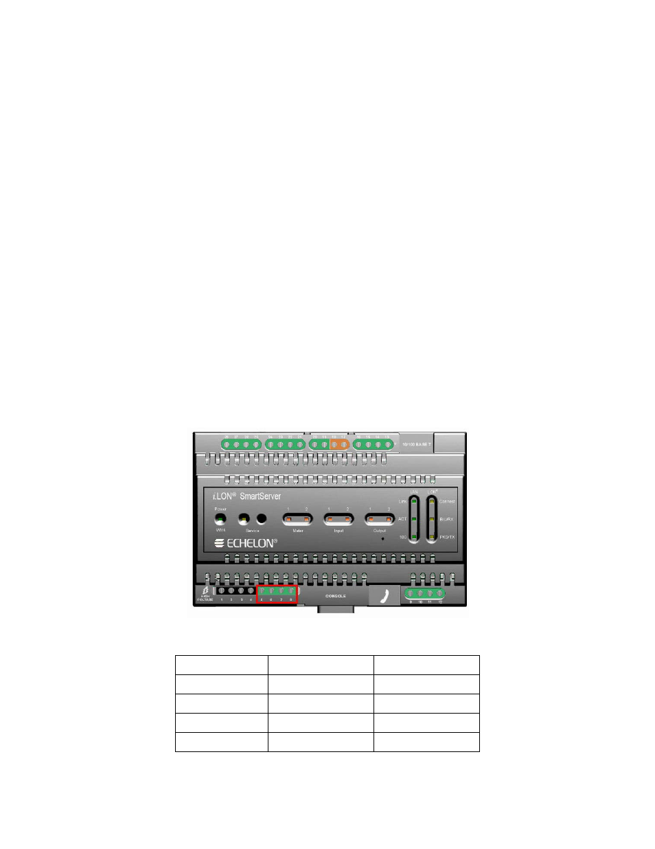
The following figure illustrates the location of the relay output screw terminals on the SmartServer.
The following table lists the enclosure markings for the relay output screw terminals on the
SmartServer and their connection type.
Screw Terminal
Enclosure Marking
Relay Connection
5
Output 1
Relay output 1
6
Output 1
Relay output 1
7
Output 2
Relay output 2
8
Output 2
Relay output 2
SmartServer 2.2 Hardware Guide
13