DuraVent DuraTech 5-8 User Manual
Page 9
9
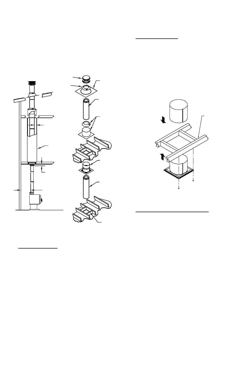
Figure 10
CAP
ADJUSTABLE
FLASHING
CHIMNEY
SECTION
ATTIC
INSULATION
SHIELD
STORM
COLLAR
FIRESTOP
RADIATION
SHIELD
CHIMNEY
SECTION
FRAMED
ENCLOSURE
2 INCH MIN
CLEARANCE
TO INSIDE OF
ENCLOSURE
REF FIG. 7
18 INCH MIN FOR
SINGLE WALL
STOVEPIPE
Figure 11
FRAMING
FIRESTOP
RADIATION SHIELD
5. Cut Roof Opening: Cut an opening in the
roof directly above the opening below, and
at least 4” larger than the chimney’s outside
diameter to provide at least a 2” clearance all
around the chimney. The chimney must be
centered within this opening and maintain the
2” clearance to combustibles.
the overlapping “U-shaped” Trim pieces so
they cover the Support Box, and secure them
to the framing members using the (6) 1-1/4”
round head wood screws provided (Fig.9).
4. Frame Openings: Frame openings in
each ceiling or floor above the Support Box
(Fig.10). These openings are to hold the
Firestop Radiation Shield and Attic Insulation
Shield. Locate each opening by dropping a
plumb bob to the four corners of the opening
below. Maintain the framing dimensions as
specified in Table 1. Warning: other than the
framing for the Reduced Clearance Support
Box, any combustible materials around
the chimney must meet the minimum 2”
clearance requirement. If Elbows must be
used to avoid an obstruction, refer to the Offset
Elbow Installation section.
6. Install Firestop Radiation Shield: A Firestop
Radiation Shield is required in multistory
installations at each floor penetration above
that where the Support Box is located.
Example: in a multistory home where the
appliance is on the ground floor (Support
Box is in the 1st floor ceiling), you would
need a Firestop Radiation Shield at the 2nd
floor ceiling, and at the 3rd floor ceiling, etc.,
including where the chimney penetrates
into the attic. Fig.10 shows a typical 2-story
installation with an attic. Note: a Firestop
Radiation Shield is not installed where the
chimney penetrates through the roof. The
Firestop Radiation Shield is installed on the
underside of the ceiling/floor framing, with the
cylindrical “tube” portion of the shield pointing
upward. (Fig.11). Use a minimum of either
(1) 8 penny nail or (1) #8, 1-1/2” wood screws
FRAMING
UNOCCUPIED
SPACE