Figure 22 – DuraVent DuraTech 5-8 User Manual
Page 15
15
Figure 21
Figure 23
to install the remainder of the Combustion Air
System. The Support Box must remain level,
and the top edge of the box must cover the
edge of the roof’s decking material. Mobile
home chimney installations are roof supported.
Do not seal openings in flashing.
A1. Place Appliance, Frame Opening:
Follow Step 1 and 2 from “Ceiling-Supported”
method detailed earlier. Refer to Table 1 for
clearance and framing specifications. If it is
desired to install through a cathedral ceiling
(Fig.20), then the hole is cut in the roof. If a
separate ceiling and roof exists, as shown in
Fig.19 (Low Attic), first cut and frame a ceiling
opening as in “Ceiling-Supported” Step 2.
A2. Install Support Box: Slip the Square
Support Box, Reduced Clearance Support
Box, or the CAS Ceiling Support into the
framed opening so the square portion projects
at least 2” below the finished ceiling and rafters
(bottom of round portion is 5” below, Fig.7),
and extends above the ceiling to framing or
decking materials to which it can be nailed.
Level the Support Box, and slit the corners to
the roofline where they extend beyond it. Bend
the flaps (created by the slitting) flush with the
roof, and nail the Support Box to the roof or
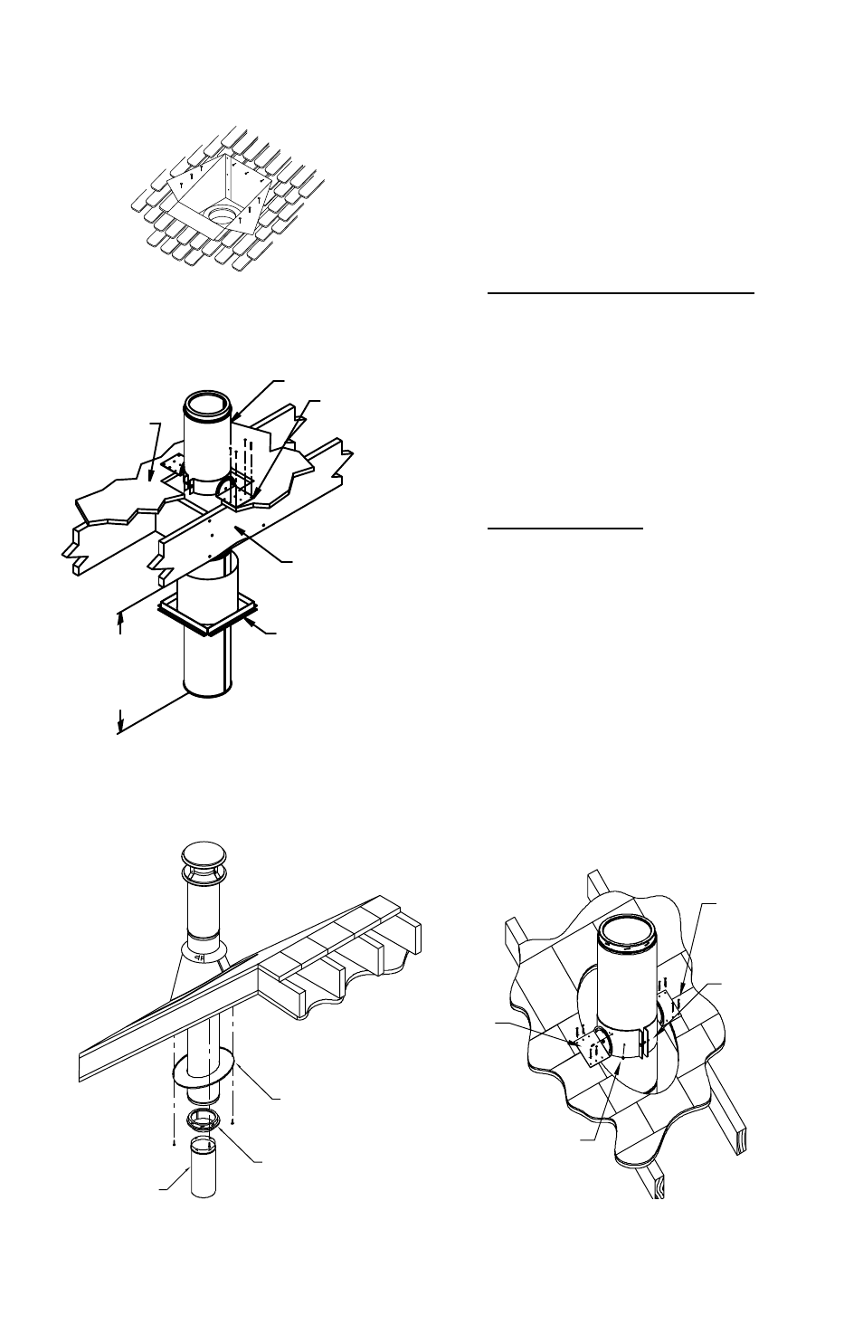
ROOF SUPPORT
TRIM COLLAR
FINISHING COLLAR
DURABLACK
SLIP CONNECTOR
USE 4 NAILS (OR
SCREWS) ON
EACH SIDE OF
SUPPORT
ROOF SUPPORT
(SUPPORT
BRACKETS AND
BAND)
SECURE ROOF
SUPPORT BAND TO
CHIMNEY USING
4 SHEET METAL
SCREWS
TIGHTEN BOLT
ON ROOF
SUPPORT BAND.
Figure 22
FLOORING
DURATECH CHIMNEY
PIPE
ROOF SUPPORT
MIN OF 3” BELOW
CEILING OR
EXPOSED FRAMING
FIRESTOP
RADIATION SHIELD
(TRIM RADIATION
SHIELD IF NEEDED
TO AVOID ROOF
SUPPORT)
FRAMING
MEMBERS
(ALL SIDES)