Method 2: roof supported installations, Figure 19 figure 20 – DuraVent DuraTech 5-8 User Manual
Page 14
14
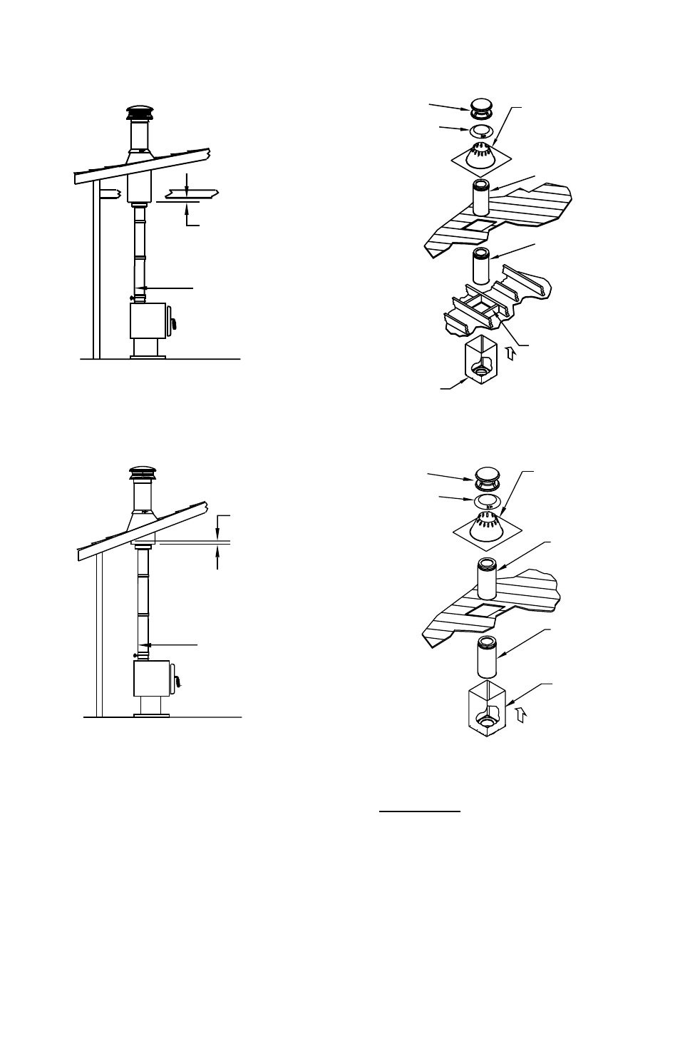
Figure 19
Figure 20
REF FIG. 7 FOR MIN
DISTANCE BELOW
CEILING FOR
SUPPORT USED
18 INCH MIN
CLEARANCE FOR
SINGLE-WALL
STOVEPIPE
CAP
ADJUSTABLE
FLASHING
CHIMNEY
SECTION
STORM
COLLAR
CHIMNEY
SECTION
FRAMED
OPENING
SQUARE
CEILING
SUPPORT BOX
OR REDUCED
CLEARANCE
SUPPORT BOX
REF FIG. 7 FOR
MIN DISTANCE
BELOW CEILING
FOR SUPPORT
USED
STOVEPIPE
CAP
ADJUSTABLE
FLASHING
CHIMNEY
SECTION
STORM
COLLAR
SQUARE
CEILING
SUPPORT BOX
OR REDUCED
CLEARANCE
SUPPORT BOX
CHIMNEY
SECTION
METHOD 2: ROOF SUPPORTED
INSTALLATIONS
There are two types of Roof Supported
Installations: (A) Using a Square Ceiling
Support Box, Reduced Clearance Support
Box, or CAS Ceiling Support; and (B) Using a
Roof Support.
(A) Support Box: For a Square Ceiling Support
Box, Reduced Clearance Support Box, or CAS
Ceiling Support installation, make sure that
the square box portion of the Support Box can
extend at least 2” below the low side of the
finished ceiling (Fig.7, 19). If the CAS Ceiling
Support is used, refer to the DuraTech CAS
Installation Instructions for directions on how
UNOCCUPIED SPACE