Warning – Dunkirk Helix VLT Vertical Laser Tube, Wall Hung Modulating Condensing Boiler User Manual
Page 40
40
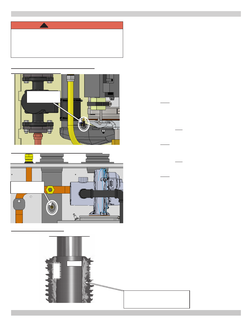
FIGURE 9-5 Combustion Analyzer Port -
050/075/100/150/200
Flame
Flame
Burner
9.6 Perform CSD-1 Compliance Test (see
paragraph 2.4 page 6)
Verify operation of boiler safety control operation with
regard to no flow conditions as follows:
1.
Turn off boiler using boiler service switch.
2.
Disable primary boiler pump. Disconnect multi pin
connector J7 from control module. See figure 9-8.
3.
Disable secondary system pumps attached to
system.
4.
Establish call for heat. Jump CHW T-T terminals
on low voltage terminal block. Turn on boiler using
boiler service switch.
5.
Boiler will fire. Based on natural convection within
boiler, boiler will either:
A. Lockout A-06 "Safety Relay Error". Requires
manual reset of control module. Press reset
button on User interface. See 9.3 Program Boiler
Control .
OR
B. Shut off burner E40 "Return Water Temp". This
is a soft lockout. When water temperature drops
below limit boiler will automatically refire then
Lockout A-06 requiring manual reset of control
module. Press Reset button on User Interface.
OR
C. Shut off burner E39 "Flue Temperature Sensor".
This is a soft lockout. When flue sensor drops
below limit, boiler will automatically refire then
Lockout A-06 requiring manual reset of control
module. Press Reset button on User Interface.
6.
After safety operation is verified, turn off boiler via
service switch. Remove jumper in T-T. Replace J7
connector into control module, enable secondary
pump operation, turn service switch on and restart
system to verify operation.
Combustion
Analyzer Port
WARNING
Asphyxiation hazard. Carbon monoxide is odorless,
tasteless, clear colorless gas, which is highly toxic.
Verify cap is firmly placed on combustion analyzer
port to prevent CO emission. Failure to do so could
result in death or serious injury.
!
FIGURE 9-7 Burner Flame
Look for BLUE flame with slight
YELLOW tips evenly spaced
around burner
FIGURE 9-6 Combustion Analyzer Port - 299
Combustion
Analyzer Port
9 - START UP PROCEDURE