Set up and adjustments – Bimba PCS Rod Lock User Manual
Page 4
Set up and adjustments
Set the deadband (page 15) The deadband adjustment changes the tolerance on the ending
position of the PFC rod. Smaller deadbands mean a tight tolerance and higher
position of the PFC rod. Smaller deadbands mean a tight tolerance and higher
positioning accuracy. Higher deadbands are required for greater loads.
1.
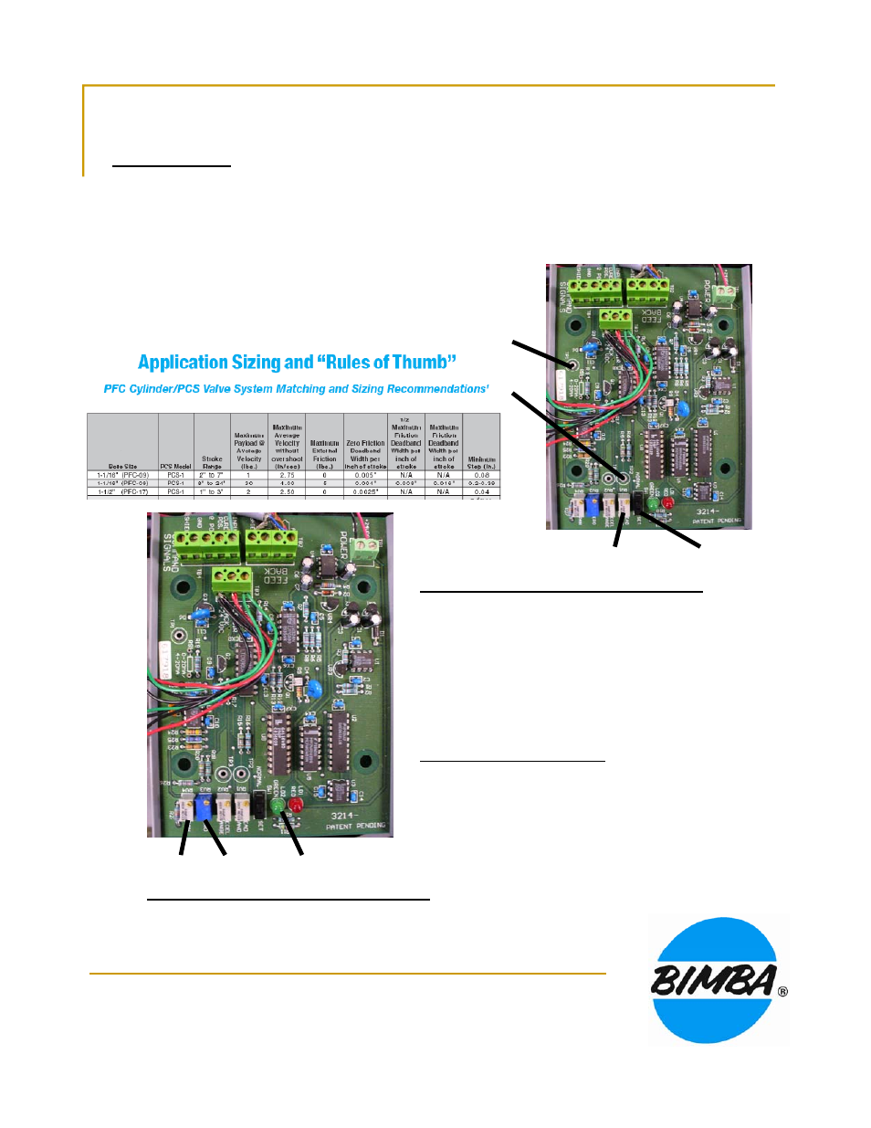
Application sizing chart (PCS manual page 23, below) identifies “Zero Friction Deadband
Voltage” for setting deadband. The deadband setting can be varied from 0.005 to 0.500 VDC.
2.
Locate TP1, TP2, SW 1, and the deadband adjustment pot.
3.
Move SW1 to SET position
4.
Set DMM to DC volts and measure between TP1 and TP2.
TP1
TP2
5.
Adjust deadband setscrew to 100 mV initially.
6.
Move SW1 to NORMAL position.
SW1
Deadband
Identify LEDs and Span and Zero adjustments.
LED’s indicate valve operation
1.
Green LED means rod is being extended: Air is
exhausted from Valve 1 (front) and pressure is applied
at valve 3 (rear)
2
Red LED means rod is being retracted: Air is
2.
Red LED means rod is being retracted: Air is
exhausted from Valve 3 (rear) and pressure is applied
at valve 1 (front).
Set the zero position (page 16)
1.
Set control voltage to 0.
2.
Turn ZERO adjust CW until rod is in the desired
retracted position (not necessarily fully retracted).
LED’s
Span
Zero
retracted position (not necessarily fully retracted).
3.
Red LED should not be on continuously.
Set the Span adjustment or end position (p.18)
1.
Set control voltage to maximum (10 VDC)
2.
Turn SPAN CCW until rod is in the desired fully extended position.
3.
The green LED should not be on continuously.