Getting started, Power up and connect air supply to demo case – Bimba PCS Rod Lock User Manual
Page 3
Getting started
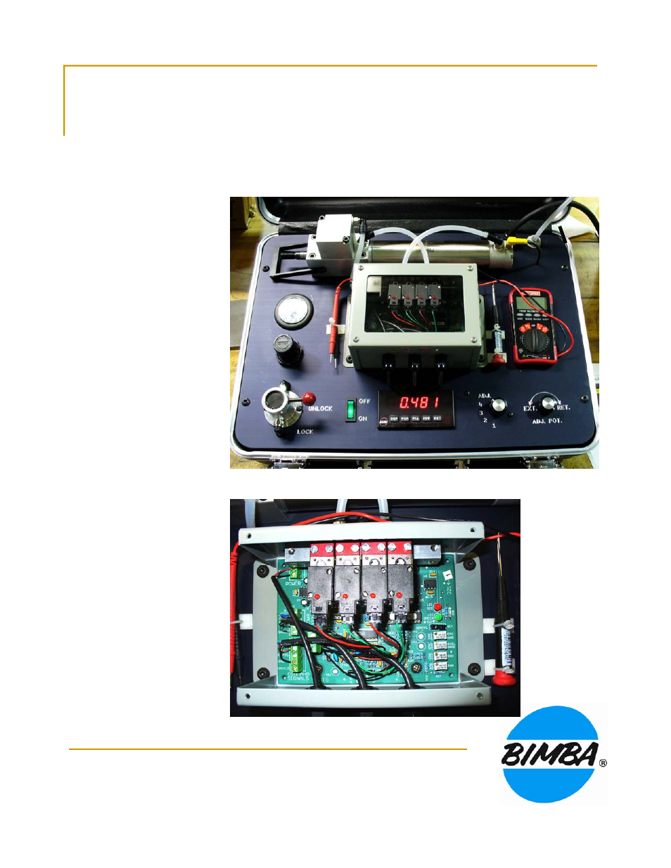
Power up and connect air supply to demo case.
Observe the connection of
air lines to cylinders and
valves (see image to the
Rod Lock
p
pp y
Be sure rod lock lever is in “UNLOCK” position.
valves (see image to the
right). Valves are part of the
PCS control. The demo
contains a DC power supply,
switch, and potentiometer,
which would normally be
supplied in the application.
The multimeter should be in
Bar
RST
1
2
3
VOLTAGE position. It ranges
from volts to millivolts; don’t
be confused by this: 1000
mV equals 1 V.
Positions 1 through 4 on the
rotary switch move the piston
R d L k L
Potentiometer
Multimeter
Rotary
S it h
DPM
3
in increments of one inch.
Position 5 switches to the
potentiometer, which moves
the piston continuously to
any position in its stroke.
The DPM is only used to
Rod Lock Lever
Potentiometer
Switch
DPM
display displacement in
inches.
Remove cover to expose the
PCS control. Review all
positions in the top three
terminal blocks They are
terminal blocks. They are
clearly marked. Electrical
connection to valves is not
required of customer for
encased controls. Identify trim
pots and LEDs, which are also
clearly labeled.