Bimba model pcs pneumatic control system, Demo case circuit diagram – Bimba PCS Rod Lock User Manual
Page 2
Bimba Model PCS Pneumatic Control
System
Learn how to:
Recognize the components required for a PCS system.
Understand how the PCS components are interconnected.
Be able to adjust Zero, Span, Deadband, Decel.
Understand basic PCS operation.
Components required for a complete closed loop system:
Components required for a complete closed loop system:
PCS electro-pneumatic controller (includes valves).
PFC, PFCN, PTF, or PTFN cylinder
Air supply (70-80 psi required for proper operation.
Regulated, filtered DC voltages.
24 VDC fixed for PCS.
0-10 VDC variable control voltage.
120 VAC line power for DPM if used.
DPM panel meter (for direct positioning readout)
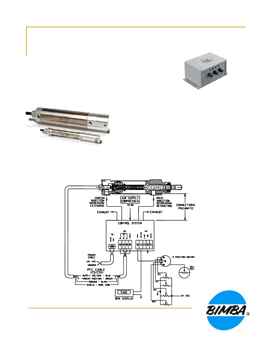
Demo Case Circuit Diagram