Step 1 – connect the system – Datalogic Scanning Reader Matrix-1000 User Manual
Page 2
MATRIX-1000™ QUICK GUIDE
2
STEP 1 – CONNECT THE SYSTEM
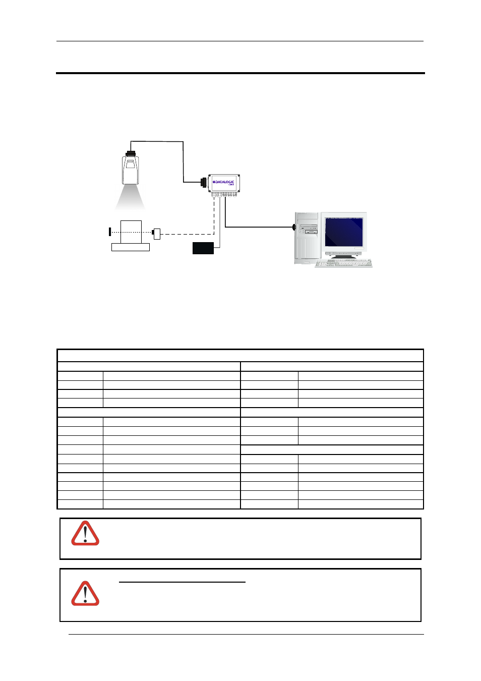
To connect the system in a Stand Alone configuration, you need the hardware indicated in Figure 1. In this layout
the data is transmitted to the Host on the RS232 auxiliary serial interface which is also used for reader
configuration by running VisiSet™.
When One Shot or Phase Mode Operating mode is used, the reader is activated by an External Trigger
(photoelectric sensor) when the object enters its reading zone.
Figure 1 – Matrix-1000™ in Stand Alone Layout
C-BOX 100 Pinout for Matrix-1000™
The table below gives the pinout of the C-BOX 100 terminal block connectors. Use this pinout when the Matrix-
1000™ reader is connected by means of the C-BOX 100:
C-BOX 100 Terminal Block Connectors
Power
Outputs
1, 3, 5
VS
21, 22
NC
2, 4, 6
GND
23, 24
NC
7, 8
EARTH GROUND
25
OUT 3+
20, 40
Reserved
26
OUT 3-
Inputs
Auxiliary Interface
RS232
27
EXT TRIG A (polarity insensitive)
35
TX AUX
28
EXT TRIG B (polarity insensitive)
37
RX AUX
29, 30
NC
38,39
GND
31, 33
NC
Main Interface
RS485 Half Duplex
32, 34
NC
11, 15
RTX 485+
36
NC
12, 16
RTX 485-
17 NC
18 NC
10, 14, 19
SGND
9,
13 RS485
Cable
Shield
CAUTION
Do not connect GND and SGND to different (external) ground references. GND and SGND
are internally connected through filtering circuitry which can be permanently damaged if
subjected to voltage drops over 0.8 Vdc.
CAUTION
When connected to a C-BOX 3x0/4x0, Matrix-1000™ can only communicate through its
Auxiliary Interface. The Matrix-1000™ 9-pin Auxiliary port connector cannot be used for
communication (i.e. configuration through VisiSet™). To configure Matrix-1000™ through
the 9-pin connector inside the C-BOX 3x0/4x0, the C-BOX 3x0/4x0 must first be
configured. See the relative C-BOX Installation Manual for details.
Matrix-1000™
CBOX-100
Local Host
PG 6000
P.S.*
* External Trigger or Presence Sensor (for One Shot or Phase mode)
CAB-600X
Aux Interface