Jumper settings – Axiomtek GOT3126T-834 User Manual
Page 20
GOT3126T-834
User’s Manual
14
Hardware and Installation
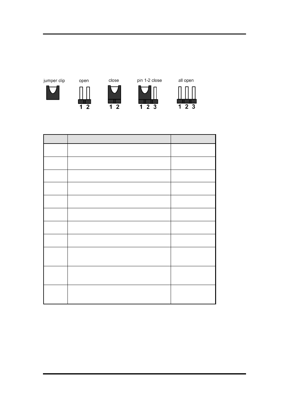
Jumper Settings
Jumper is a small component consisting of jumper clip and jumper pins. Install jumper clip on 2
jumper pins to close. And remove jumper clip from 2 jumper pins to open. The following
illustration shows how to set up jumper.
Making the proper jumper settings configure the SBC87834 to match the needs of your
application. The following table shows the default jumper settings for the onboard devices.
Jumper
★ Default Setting
Jumper Setting
JP1
★ Panel backlight control PWM mode
Panel backlight control DC mode
Short 1-2
Short 3-4
JP2
Touch Controller 4,8 WIRE
★ Touch Controller 5 WIRE
Short 1-2
Short 2-3
JP4
★ LVDS Panel Power : 3.3V
LVDS Panel Power : 5V
Short 1-2
Short 2-3
JP5
Touch OFF
★ Touch ON
Short 1-2
Short 2-3
JP6
★ PCIe device
mSATA device
Short 1-2
Short 2-3
JP7
AT mode
★ ATX mode
Short 1-2
Short 2-3
JP8
★ Normal
Clear CMOS
Short 1-2
Short 2-3
JP11
COM3_5VSB
★ COM3_5V
Short 1-2
Short 2-3
JP12
★ COM1 normal mode
COM1 pin1 with power :+5V
COM1 pin9 with power :+12V
Short 3-5,4-6
Short 1-3,4-6
Short 3-5,2-4
JP13
★ COM2 normal mode
COM2 pin1 with power :+5V
COM2 pin9 with power :+12V
Short 3-5,4-6
Short 1-3,4-6
Short 3-5,2-4
JP14
★ COM3 normal mode
COM3 pin1 with power :+5V
COM3 pin9 with power :+12V
Short 3-5,4-6
Short 1-3,4-6
Short 3-5,2-4