Avalue EEV-EX03 User Manual
Page 29
Quick Installation Guide
EEV-EX03 Quick Installation Guide 29
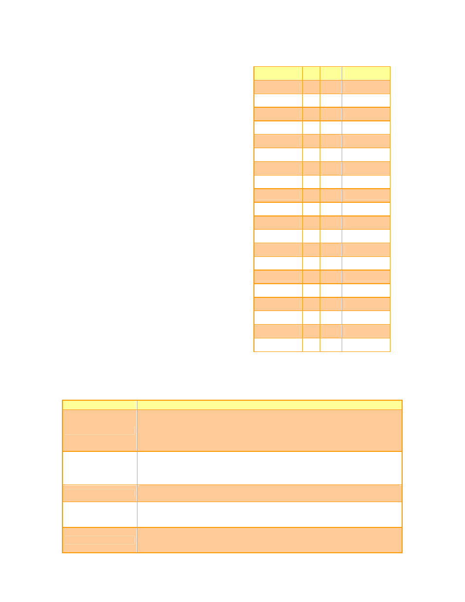
Signal
PIN PIN
Signal
SA10
B61 B62
REFCH#
SA11
B63 B64
DREQ1
SA12
B65 B66
DACK#1
GND
B67 B68
GND
SA13
B69 B70
DREQ3
SA14
B71 B72
DACK#3
SA15
B73 B74
IOR#
SA16
B75 B76
IOW#
SA18
B77 B78
SA17
SA19
B79 B80
SMEMR#
IOCHRDY
B81 B82
AEN
+5V
B83 B84
+5V
SD0
B85 B86
SMEMW#
SD2
B87 B88
SD1
SD3
B89 B90
NOWS#
DREQ2
B91 B92
SD4
SD5
B93 B94
IRQ9
SD6
B95 B96
SD7
IOCHK#
B97 B98
RSTDRV
GND
B99 B100
GND
2.3.29 Signal Description – ETX Connector 2 (ETX2)
2.3.29.1 ISA Signals
Signal
Signal Description
SD[0:15]
These signals provide data bus bits 0 to 15 for any peripheral devices. All 8-bit
devices use SD[0:7] for data transfers. 16-bit devices use SD[0:15].
To support 8-bit devices, the data on SD[8:15] is gated to SD[0:7] during 8-bit
transfers to these devices. 16-bit CPU cycles will be automatically converted into
two 8-bit cycles for 8-bit peripherals.
SA[0:19]
Address bits 0 through 15 are used to address I/O devices. Address bits 0 through
19 are used to address memory within the system. These 20 address lines, in
addition to LA[17:23] allow access of up to 16MB of memory. SA[0:19] are gated
on the ISA-bus when BALE is high and latched on to the falling edge of BALE.
SBHE#
Bus High Enable indicates a data transfer on the upper byte of the data bus
SD[8:15]. 16-bit I/O devices use SBHE# to enable data bus buffers on SD[8:15].
BALE
BALE is an active-high pulse generated at the beginning of any bus cycle initiated
by a CPU module. It indicates when the SA[0:19], LA17.23, AEN, and SBHE#
signals are valid.
AEN
AEN is an active-high output that indicates a DMA transfer cycle. Only resources
with a active DACK# signal should respond to the command lines when AEN is
high.