Jumper and connector list – Avalue ENX-CDD User Manual
Page 14
ENX-CDD User
’s Manual
14 ENX-CDD User
’s Manual
2.3 Jumper and Connector List
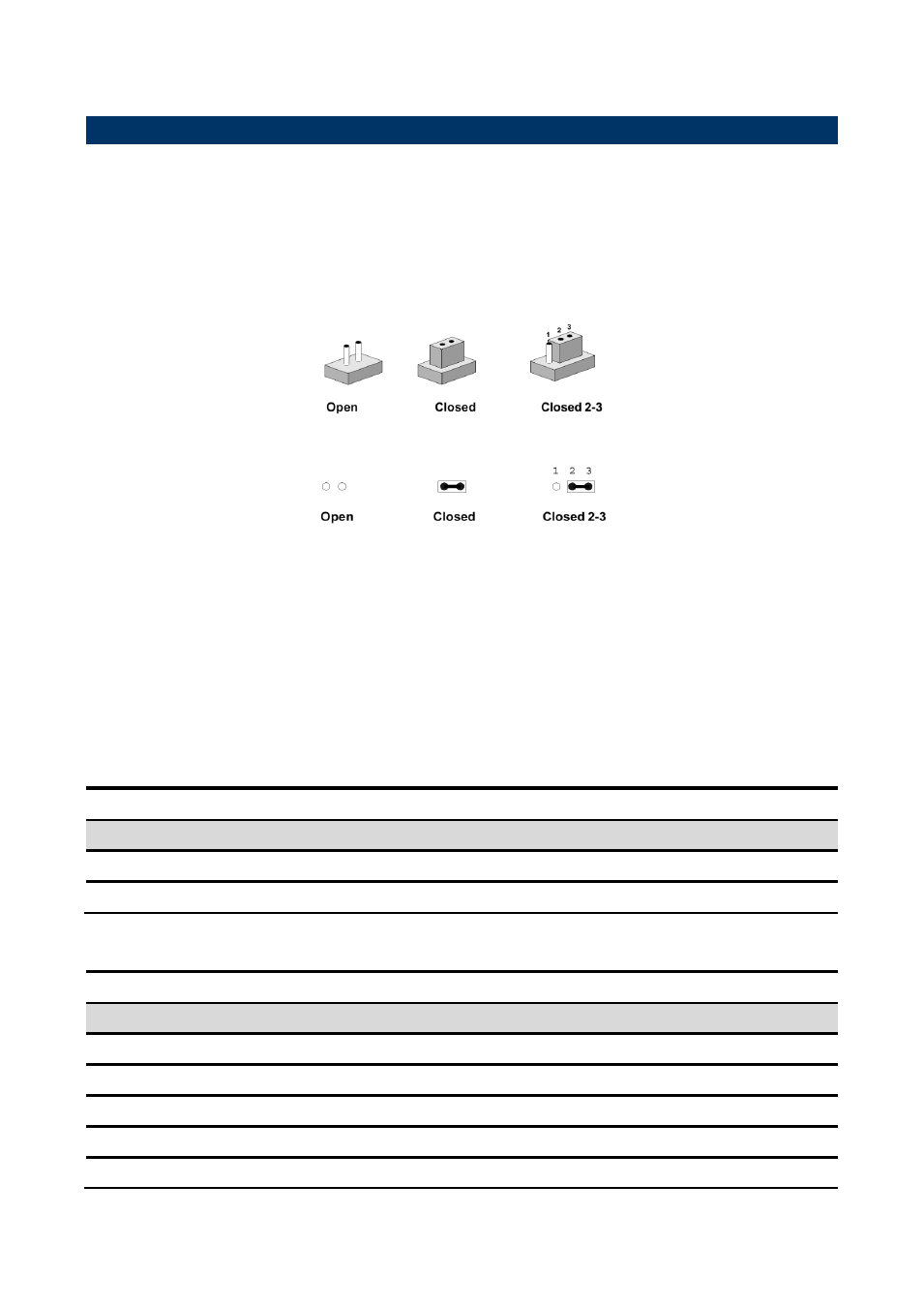
You can configure your board to match the needs of your application by setting jumpers. A
jumper is the simplest kind of electric switch.
It consists of two metal pins and a small metal clip (often protected by a plastic cover) that
slides over the pins to connect them. To “close” a jumper you connect the pins with the clip.
To “open” a jumper you remove the clip. Sometimes a jumper will have three pins, labeled 1,
2, and 3. In this case, you would connect either two pins.
The jumper settings are schematically depicted in this manual as follows:
A pair of needle-nose pliers may be helpful when working with jumpers.
Connectors on the board are linked to external devices such as hard disk drives, a
keyboard, or floppy drives. In addition, the board has a number of jumpers that allow you to
configure your system to suit your application.
If you have any doubts about the best hardware configuration for your application, contact
your local distributor or sales representative before you make any changes.
The following tables l
ist the function of each of the board’s jumpers and connectors.
Jumpers
Label
Function
Note
JS1/2
mSATA/Mini PCIe function Jumper
3 x 2 header, pitch 2.54 mm
JP1
LVDS voltage
3 x 1 header, pitch 2.54 mm
Connectors
Label
Function
Note
BAT1
Battery connector
2 x 1 wafer, pitch 1.25 mm
JPCIE
PCIE signal selector
14 x 1 wafer, pitch 1.00 mm
J_RST
Reset connector
2 x 1 header, pitch 2.54 mm
HDMI1
HDMI connector
J2
SD/MS/MMC socket