Able of interfaces, Technical data and information, Figure 5: location of controls, right side view – ADLINK MLC 4-21 User Manual
Page 13: Figure 6: detail right side view, keys and leds
MLC 4-xx
Technical Manual Rev. 1.2
Description of interfaces and
functions
Document: Manual_Medical_MLC_1.2
Page 13 of 37 pages
Last change date: 18-Feb-15
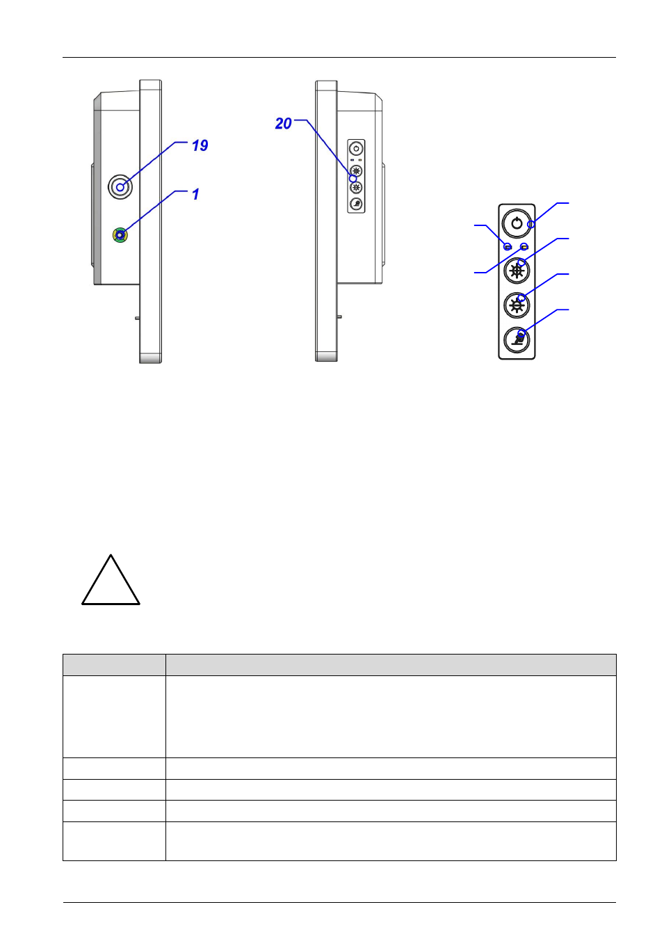
Figure 4: Location of interfaces
and controls, left side view
Figure 5: Location of controls, right
side view
Figure 6: Detail right side view, keys
and LEDs
6.1.2. Table of interfaces
– technical data and information
Note: The numbers in the figures of the previous chapter correspond with the enumeration of the suc-
ceeding table.
Do not connect or disconnect a powered supply cable to your PENTA device.
Attach only depowered supply cables to the PENTA device and connect the
power supply cable thereafter to the power source/outlet.
Interface #
Description
1
Potential equalization plug,
6mm, according to DIN 42801 with yellow/green
color code washer
Note: The equipment bonding terminal of the unit has to be connected to
the equipotential bonding strip (see IEC 60601-1 / EN 60601-1 or equivalent
national standards).
2
AC power input, 3pos, IEC 60320 type C14, medical version w/o Y capacitors
3
Optional DVI-D output
4 & 13
HDMI V1.4a compliant output
5
COM1, RS-232 serial port, max 115200b/s transfer speed
Note: Resources (I/O address, IRQ line) are managed via BIOS settings
20a
20b
20c
20d
20e
20f
!