Table 8, Mc-2 connector pin signals – ADLINK MilSystem 800 User Manual
Page 15
MilSystem Setup
MilSystem
User’s Guide
11
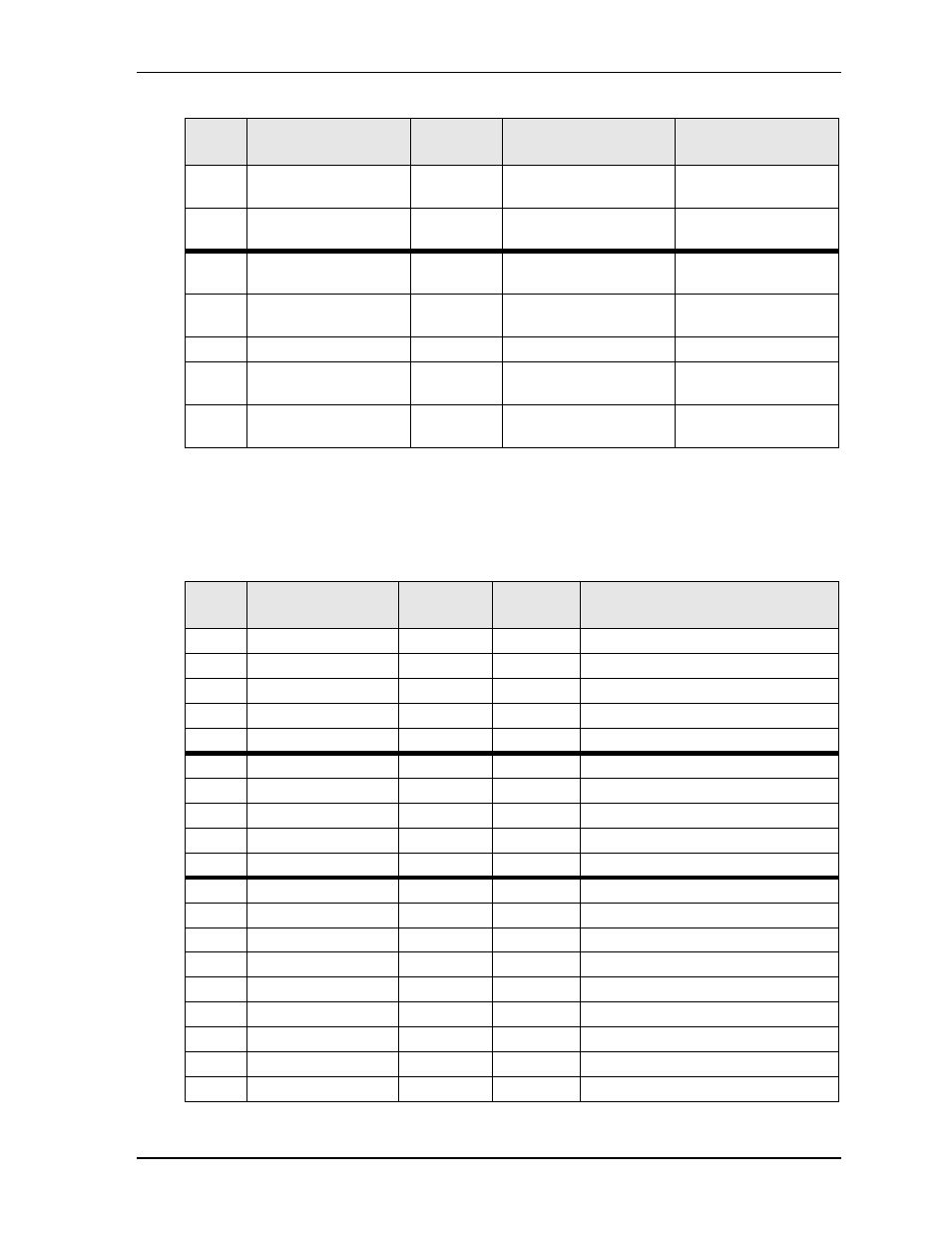
*Supported only on MilSystem 735
**Supported only on MilSystem 840
***Supported only on MilSystems 735 and 840
48**
LED (Red)
2
HDDLED (Cathode)
Indicates Hard Drive
Activity
49**
LED (Red)
1
HDDLED_+5V (Anode) Indicates Hard Drive
Activity
51***
SATA
2
SATA_TXP0
SATA0 Transmit
Positive
52***
SATA
3
SATA_TXN0
SATA0 Transmit
Negative
53***
SATA
1, 4, 7
SATA_GND
Ground
54***
SATA
5
SATA_RXN0
SATA0 Receive
Negative
55***
SATA
6
SATA_RXP0
SATA0 Receive
Positive
Table 8. MC-2 Connector Pin Signals
Pin #
Breakout Cable
Connector
Breakout
Cable Pin #
Signal
Signal Description
1
USB3
1
USBPWR3 Power
2
USB3
2
USBP-3
Data Negative
3
USB3
3
USBP+3
Data Positive
4
USB3
4
USBGND3 Ground
5
USB3
SH
SHIELD3
Shield
6
USB4
1
USBPWR4 Power
7
USB4
2
USBP-4
Data Negative
8
USB4
3
USBP+4
Data Positive
9
USB4
4
USBGND4 Ground
55
USB4
SH
SHIELD4
Shield
10
Ethernet
1
MDI0_P
Ethernet0 Positive
11
Ethernet
2
MDI0_N
Ethernet0 Negative
12
Ethernet
3
MDI1_P
Ethernet1 Positive
13
Ethernet
4
MDI2_P
Ethernet2 Positive
14
Ethernet
5
MDI2_N
Ethernet2 Negative
15
Ethernet
6
MDI1_N
Ethernet1 Negative
16
Ethernet
7
MDI3_P
Ethernet3 Positive
17
Ethernet
8
MDI3_N
Ethernet3 Negative
54
Ethernet
SH
SHIELD
Ethernet0, 1, 2, 3 Shield
Table 7. MC-1 Connector Pin Signals (Continued)
MC
Pin #
Breakout Cable
Connector
Breakout
Cable Pin #
Signal
Signal Description