Connecting peripherals, Figure 3, Flat view of milsystem i/o panel – ADLINK MilSystem 800 User Manual
Page 12: 8user’s guide milsystem, Figure 3. flat view of milsystem i/o panel, Milsystem setup, Mc-3 mc-2 mc-1 power
MilSystem Setup
8
User’s Guide
MilSystem
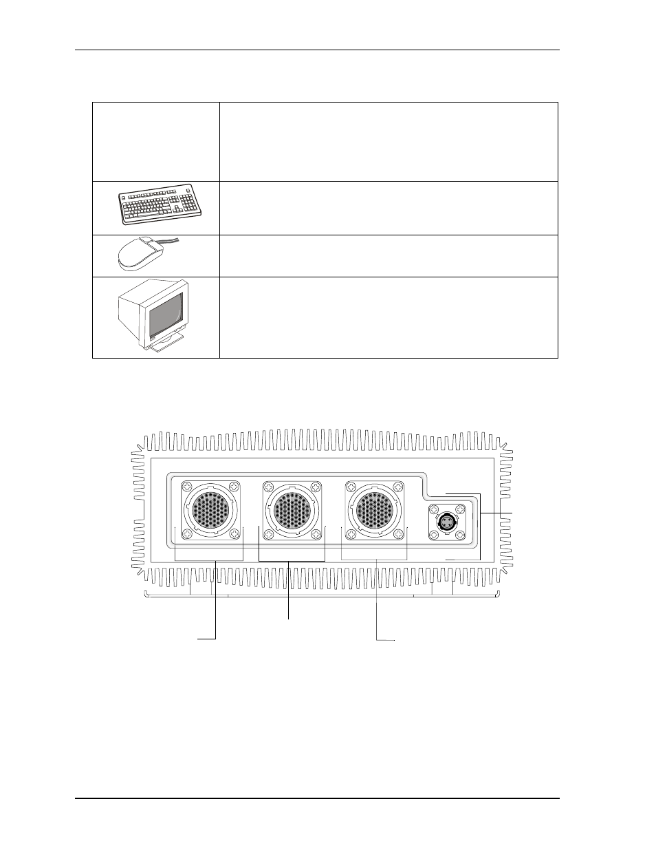
Figure 3. Flat View of MilSystem I/O Panel
Connecting Peripherals
7) Connect the MC-1 cable
to the MilSystem. See
illustrations of cables. See
for locations of
the MC connectors.
•
Refer to
for locations and descriptions of the connectors before
making connections or powering on the MilSystem.
•
Connect the USB or PS2 keyboard to the appropriate connector on the
MC-1 connector.
•
Connect the USB mouse (PS2 not supported) to the appropriate connec-
tor on the MC-1 connector.
•
Connect the CRT or LCD monitor through its 15-pin cable to the VGA
cable on the MC-1 connector.
47
40
25
32
17
10
4
1
3
9
16
24
31
39
46
52
55
53
47
40
25
32
17
10
4
1
3
9
16
24
31
39
46
52
55
53
47
40
25
32
17
10
4
1
3
9
16
24
31
39
46
52
55
53
B
AD
C
8-4
MC-3
MC-2
MC-1
POWER
DC
Power
In
MC-3 - Parallel
and LVDS
MC-2 - USB3,
USB4, Fast
Ethernet, and
RS232/485/422
COM Ports
MC-1 - VGA, Ethernet,
PS2 Keyboard, Stereo
Audio Out, Stereo Line In,
Mic In, Power Button,
Reset Button, Power LED,
HDD Activity LED, SATA,
USB1 and USB2