ADLINK MilSystem 800 User Manual
Page 14
MilSystem Setup
10
User’s Guide
MilSystem
15
Ethernet
3
MDI1_P
Ethernet1 Positive
16
Ethernet
4
MDI2_P
Ethernet2 Positive
17
Ethernet
5
MDI2_N
Ethernet2 Negative
18
Ethernet
6
MDI1_N
Ethernet1 Negative
19
Ethernet
7
MDI3_P
Ethernet3 Positive
20
Ethernet
8
MDI3_N
Ethernet3 Negative
21
USB1
1
USBPWR1
Power
22
USB1
2
USBP-1
Data Negative
23
USB1
3
USBP+1
Data Positive
24
USB1
4
USBGND1
Ground
25
USB1
SH
SHIELD
USB1 Shield
26
USB2
1
USBPWR2
Power
27
USB2
2
USBP-2
Data Negative
28
USB2
3
USBP+2
Data Positive
29
USB2
4
USBGND2
Ground
35
USB2
SH
SHIELD
USB2 Shield
30
PS2
1
KBD_DATA
Keyboard Data
31
PS2
SH
KBD_SHIELD
Keyboard Shield
32
PS2
3
GND4
Ground
33
PS2
4
KBD_PWR (VCC)
Keyboard Power
34
PS2
5
KBD_CLK
Keyboard Clock
36
Green Audio
1
HP_L
Stereo Audio Out Left
37
Green Audio
2
HP_R
Stereo Audio Out Right
38
Green Audio
3
HP_GND
Stereo Audio Out
Ground
39
Pink Audio
1
MIC1_IN
Microphone In
40
Pink Audio
3
MIC_GND
Microphone Ground
41
Pink Audio
2
MIC_REF
Microphone Reference
42
Blue Audio
1
LINE_IN_L
Stereo Line In Left
Channel
43
Blue Audio
3
LINE_IN_GND
Stereo Line In Ground
44
Blue Audio
2
LINE_IN_R
Stereo Line In Right
Channel
45
Push button
1
PowerOn
Powers On the system
50
Push button
2
GND
Ground
46
Push button
1
Reset
Resets the system
50
Push button
2
GND
Ground
47
LED (Green)
1
PowerLED
Indicates Power On
50
LED (Green)
2
GND
Ground
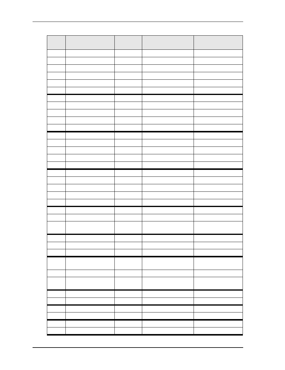
Table 7. MC-1 Connector Pin Signals (Continued)
MC
Pin #
Breakout Cable
Connector
Breakout
Cable Pin #
Signal
Signal Description