Table 2-2: led indicators – ADLINK MXE-5300 Series User Manual
Page 20
10
System Description
2.2.1
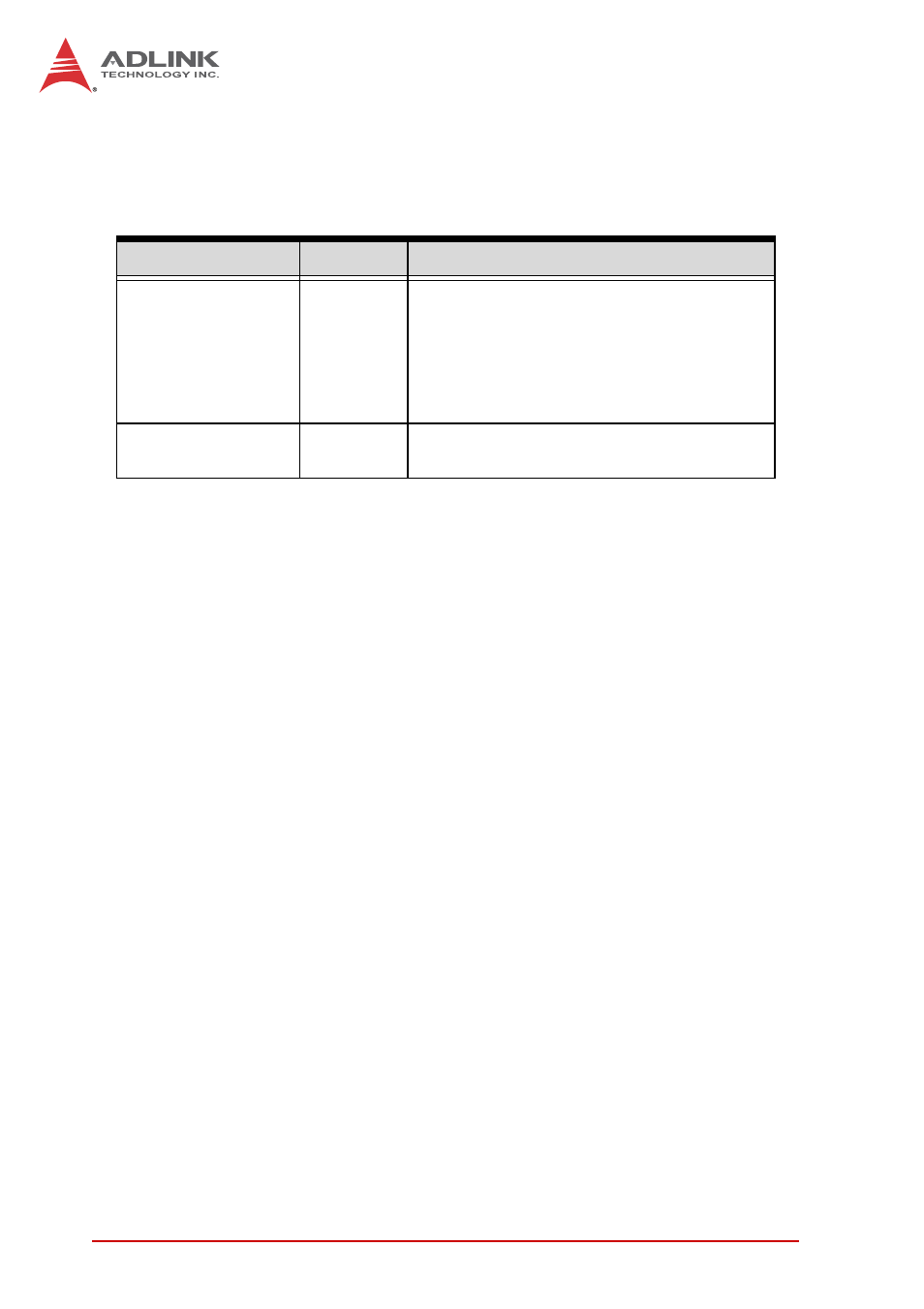
LED Indicators
In addition to the LED of the power switch, two LEDs on the front
panel indicate the following.
Table 2-2: LED Indicators
2.2.2
Power Switch
The power switch is non-latched, with a blue LED indicator. Sys-
tem is turned on when the button is depressed, and the power
LED lights. If the system hangs, depressing the switch for 5 sec-
onds turns the system off completely.
2.2.3
Reset Button
The reset button executes a hard reset.
2.2.4
PS/2 Connector
The MXE-5300 provides connectors for PS/2 keyboard and
mouse, either singly or with a Y-cable to connect both at the same
time.
LED indicator
Color
Description
Diagnostic
Yellow
X
If lit continuously, indicates no
physical storage is connected
X
If blinking, indicates no mem-
ory is installed on either SO-
DIMM socket
HDD
Green
When blinking, indicates the SATA hard
drive is active
- USB-1901 (84 pages)
- USB-1210 (54 pages)
- USB-2401 (60 pages)
- USB-7230 (50 pages)
- USB-2405 (56 pages)
- DAQe-2010 (92 pages)
- DAQe-2204 (100 pages)
- DAQe-2213 (94 pages)
- DAQe-2501 (74 pages)
- PXI-2010 (84 pages)
- PXI-2020 (60 pages)
- PXI-2501 (62 pages)
- cPCI-9116 (98 pages)
- ACL-8112 Series (93 pages)
- ACL-8112 Series (94 pages)
- ACL-8112 Series (92 pages)
- ACL-8216 (75 pages)
- ACL-8111 (61 pages)
- PCM-9112+ (10 pages)
- PCM-9112+ (94 pages)
- cPCI-6216V (47 pages)
- ACL-6126 (28 pages)
- ACL-6128A (40 pages)
- PCM-6308V+ (4 pages)
- PCM-6308V+ (52 pages)
- PCI-7444 (82 pages)
- PCI-7434 (48 pages)
- PCI-7234 (56 pages)
- PCI-7260 (66 pages)
- PCI-7258 (38 pages)
- PCI-7256 (48 pages)
- PCI-7250 (48 pages)
- LPCI-7250 (48 pages)
- PCI-7396 (65 pages)
- PCI-7296 (59 pages)
- PCI-8554 (67 pages)
- PCIe-7360 (94 pages)
- PCIe-7350 (86 pages)
- PCIe-7300A (114 pages)
- PCIe-7200 (51 pages)
- PCI-7300A (112 pages)
- PCI-7300A (83 pages)
- PCI-7200 (96 pages)
- cPCI-7300 (82 pages)
- cPCI-7300 (83 pages)