ADLINK cExpress-BT2 User Manual
Page 27
cExpress-BT2
Page 27
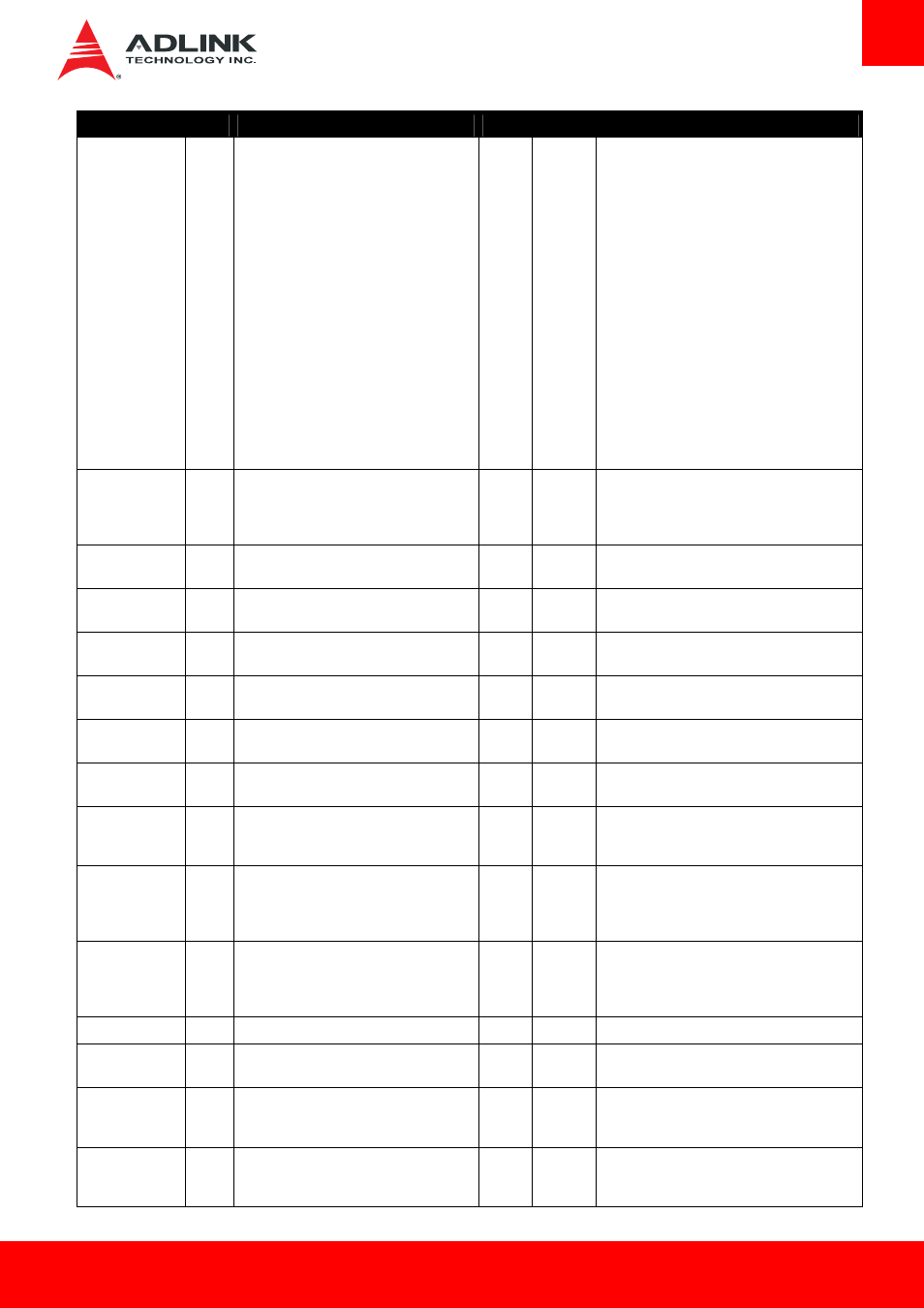
Signal
Pin #
Description
I/O
PU/PD
Comment
PCI_AD13
PCI_AD14
PCI_AD15
PCI_AD16
PCI_AD17
PCI_AD18
PCI_AD19
PCI_AD20
PCI_AD21
PCI_AD22
PCI_AD23
PCI_AD24
PCI_AD25
PCI_AD26
PCI_AD27
PCI_AD28
PCI_AD29
PCI_AD30
PCI_AD31
D29
C32
D30
D37
C39
D38
C40
D39
C42
D40
C43
D42
C45
D43
C46
D44
C47
D45
C48
PCI_C/BE0#
PCI_C/BE1#
PCI_C/BE2#
PCI_C/BE3#
D26
C33
C38
C44
PCI bus byte enable lines, active low
I/O
3.3V
PCI_DEVSEL#
C36
PCI bus Device Select, active low.
I/O
3.3V
PU 8k2
3.3V
PCI_FRAME#
D36
PCI bus Frame control line, active low.
I/O
3.3V
PU 8k2
3.3V
PCI_IRDY#
C37
PCI bus Initiator Ready control line, active
low.
I/O
3.3V
PU 8k2
3.3V
PCI_TRDY#
D35
PCI bus Target Ready control line, active
low.
I/O
3.3V
PU 8k2
3.3V
PCI_STOP#
D34
PCI bus STOP control line, active low, driven
by cycle initiator.
I/O
3.3V
PU 8k2
3.3V
PCI_PAR
D32
PCI bus parity
I/O
3.3V
PCI_PERR#
C34
Parity Error:
An external PCI device drives PERR# when it
receives data that has a parity error.
I/O
3.3V
PU 8k2
3.3V
PCI_REQ0#
PCI_REQ1#
PCI_REQ2#
PCI_REQ3#
C22
C19
C17
D20
PCI bus master request input lines, active
low.
I 3.3V
PU 8k2
3.3V
PCI_GNT0#
PCI_GNT1#
PCI_GNT2#
PCI_GNT3#
C20
C18
C16
D19
PCI bus master grant output lines, active low. O 3.3V
PCI_GNT[0..3]# are boot strap signals (see note
below)
PCI_RESET#
C23
PCI Reset output, active low.
O 3.3V
PCI_LOCK#
C35
PCI Lock control line, active low.
I/O
3.3V
PU 8k2
3.3V
PCI_SERR#
D33
System Error: SERR# may be pulsed active
by any PCI device that detects a system error
condition.
I/O
3.3V
PU 8k2
3.3V
PCI_PME# C15
PCI
Power
Management Event: PCI
peripherals drive PME# to wake system from
low-power states S1–S5.
I
3.3VSB