Bios boot setup screen, Figure 4-4 – ADLINK Express-HRR User Manual
Page 45
Chapter 4
BIOS Setup
Express-HRR
Reference Manual
41
♦
USB Configuration
•
EHCI1 [Enabled; Disabled]
•
EHCI2 [Enabled; Disabled]
♦
PCI Express Configuration
•
Target Link Speed [GEN1; GEN2]
•
PCIE Ports 1-4 Configuration [Four X1 Ports; One X4 Port]
•
PCI Express Root Port 1 (Main Switch) [Disabled; Enabled]
•
PCI Express Root Port 2 [Disabled; Enabled]
•
PCI Express Root Port 3 [Disabled; Enabled]
•
PCI Express Root Port 4 [Disabled; Enabled]
•
PCI Express Root Port 5 [Disabled; Enabled]
•
PCI Express Root Port 6 [Disabled; Enabled]
•
PCI Express Root Port 7 [Disabled; Enabled]
•
PCI Express Port 8 is assigned to LAN
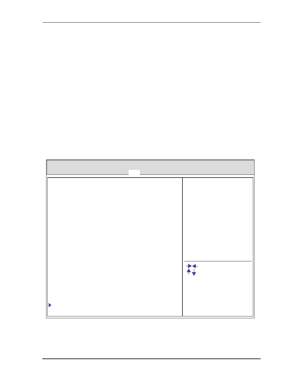
BIOS Boot Setup Screen
Figure 4-4. BIOS Boot Setup Screen
Express-HRR REV : XXX
Boot Configuration
Set Boot Priorities
CSM16 Module Version XX.XX
Version X.XX.XXXX. Copyright (C) 20XX American Megatrends, Inc.
Express-HRR_BIOS_Boot_a
Main Advanced Chipset Boot Security Save & Exit
Setup Prompt Timeout 1
Quiet Boot
[Disabled]
Bootup NumLock State [On]
Option ROM Messages [Force BIOS]
GateA20 Active [Upon Request]
Interrupt 19 Capture
[Enabled]
1st Boot
[CD/DVD]
2nd Boot
[Hard Disk : Xxxxxxxx]
3rd Boot
[USB Floppy]
4th Boot
[USB CD/DVD]
5th Boot
[USB Hard Disk]
6th Boot
[USB Key]
7th Boot
[Network]
8th Boot
[UEFI]
Hard Drive BBS Priorities
[Setting Description]
: Select Screen
: Select Item
+/- : Change field
F1 : General Help
Enter : Select
F2 : Previous Values
F3&F9 : Optimized Defaults
F4 : Save & Exit
F10 : Save & Reset
ESC: Exit